Local Operation
GO/NG Output Port Connector
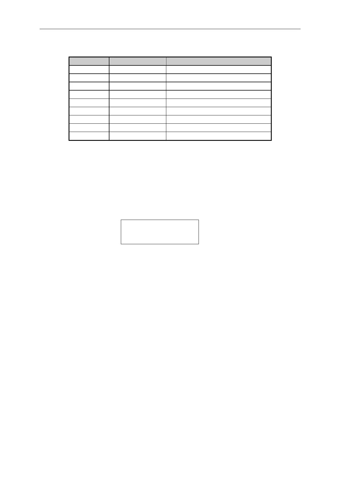
Pin Number Channel No. Description
1 1 H:PASS or SPEC. OFF, L:FAIL
3 2 H:PASS or SPEC. OFF, L:FAIL
5 3 H:PASS or SPEC. OFF, L:FAIL
7 4 H:PASS or SPEC. OFF, L:FAIL
9 5 H:PASS or SPEC. OFF, L:FAIL
11 6 H:PASS or SPEC. OFF, L:FAIL
13 7 H:PASS or SPEC. OFF, L:FAIL
15 8 H:PASS or SPEC. OFF, L:FAIL
8 Enable H:SPEC. OFF, L:SPEC. ON
Note: Pin 2, 4, 6, 10, 12, 14 are connected to GND.
4.2.13 Setting the GPIB Address
Please refer to the High Speed DC Electronic Load 6330 Series Programming Manual for
GPIB address appears after RS-232C parameters in the system. You can use this feature to
check GPIB address.
GPIB ADDRESS 1
4.2.14 Using the Synchronous Cable
6330 Series supports up to 5 sets of mainframe synchronous load control, see 4.2.6 for the
configuration setting. The connection between mainframe is via the RS-232C connector on
the rear panel. Figure 4-6 shows the internal wiring of synchronous cable and MASTER/
SLAVE connection of mainframe. It requires another synchronous cable if one more
SLAVE is desired. Be sure to connect the MASTER port to the EXTENDED port of
previous cable and plug in the SLAVE port to mainframe, and so forth.
4-17

 Loading...
