Programmable DC Electronic Load 6310 Series Operation & Programming Manual
4.2.10 Lock Operation
The lock operation disables all settings for change. When the data is locked, all settings
cannot be changed. The operation of ON/OFF and SPEC keys will not be affected by lock
function. Press SHIFT and . simultaneously to enable/disable lock function.
4.2.11 Setting System and RS-232C Connection
The parameters of RS-232C are set in the system. There are three parameters for you to set:
Baud Rate, Parity Check and Data Bit number. Press SHIFT and 0 simultaneously to set the
system data.
Baud Rate: 0:600, 1:1200, 2:2400, 3:4800, 4:9600 bits/second.
Parity Check: 0:EVEN, 1:ODD, 2:NONE.
Data Bit: 0:7 bits, 1:8 bits.
The RS-232C connector on the Mainframe rear panel is a 9-pin connector (DB-9, male
connector). The RS-232C connector bus signal is defined as follows.
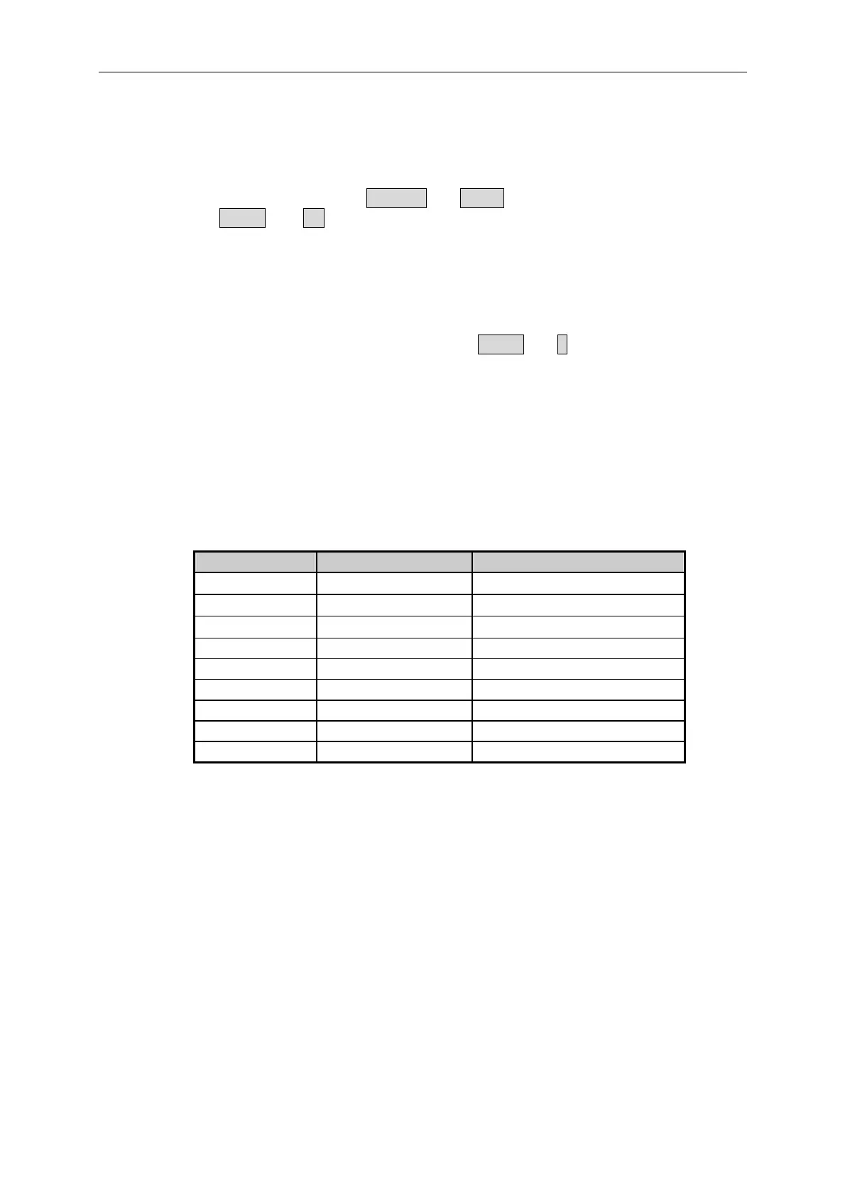
RS-232C Connector
Pin Number Input/Output Description
1 Output
+5V
2 Input
R×D
3 Output
T×D
4 Output DTR
5 Output GND
6 Input DSR
7 NC
8 NC Master Input/Slave Output
9 NC Maser Output/Slave Input
Note: Pin 1 (+5V) is for 6310 Series Remote Controller only.
4.2.12 Connecting the GO/NG Output Port
The GO/NG output port on the Mainframe rear panel is a 15-pin connector (DB-15, female
connector). The GO/NG signals are TTL active low to indicate NG. They are defined as
follows.
4-16

 Loading...
