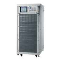
Programmable DC Electronic Load 6310 Series Operation & Programming Manual
function as single channel/module. When the LEDs of channel R and L are on, the
LED of operation mode indicators will be disabled (off). The GO/NG LED turns to red
when the channel SPEC checking fails. It will turn to green when the SPEC checking
of both channels is all right.
5. Keypad Indicators
There are three LEDs to indicate the keypad status. Each LED shows the key status.
It has the same function as single channel/module. The LED of LOAD will be active
when either input of channel L or R is on.
6. Keypad
There are four keys for you to select /control the operation of Load module. The
R/L key is used to select the display of 7-segment LED, and the indicators of channel R
and/or L. The R/L key can be used to select fix mode for rotary knob setting too.
Please refer to section 4.3.3.
7. Vsense Connectors
These four connectors are for Vsense measurement input. The two connectors on the
right are for right channel while those on the left is for left channel. Refer to section
2.5.2 for remote sensing connections.
8. Rotary Knob
The knob has the same function as single channel/module when channel R or L is
selected. If the indicators of channel R and L are on, the knob will be disabled.
9. Load Terminals
They are input connectors for the Load to connect with the UUT. The two Terminals
on the left are for input of left channel while those on the right are for the right channel.
The PLUS (+) sign of each channel input must connect to the high potential. Refer to
section 2.5.1 for load input connections.
Examples
Following examples illustrate how to select the double channels module in CC mode.
You have to select right or left channel for display & keypad for the double channels module.
When channel R and L is selected; only R/L key is enabled. Other keys are disabled.
During power-on, the pre-selected channel is channel L. It means the 7-segment display,
indicators and keypad are active for channel L. The double channels module has the same
function as single channel module, except it cannot select level 2 (B).
The display sequence of R/L key is channel L -> channel R -> channels L+R display V ->
channels L+R, then back to channel L.
1. Select Dynamic Function
The static and dynamic function can be selected through the STATIC/DYNA key. Press
this key to select Dynamic function, and press it again to select static function. When
Dynamic function is selected, the LED of DYNAmic will be active.
4-22

 Loading...