Installation 2-5
5160 Service Aggregation Switch Hardware Installation and Start-up Manual
009-3207-001 Standard Revision A
Copyright
©
2013 Ciena
®
Corporation September 2013
Grounding
The 5160 is connected to ground at the power supplies and the chassis.
Note: The Battery Return lead is considered DC-I (isolated from frame
ground) as described in GR-1089-CORE, Issue 6.
Power Supply Grounding
The safety ground connection is provided by the AC power cord or by the
grounding terminal on the DC power supply. Further details are provided in
“Power Supply Modules” on page 2-6.
Supplemental Ground
A supplemental ground connection is provided for connection to a Common
Bonding Network (CBN). The grounding screws are supplied and are located
in the center on the rear of the chassis. See Figure 2-1.
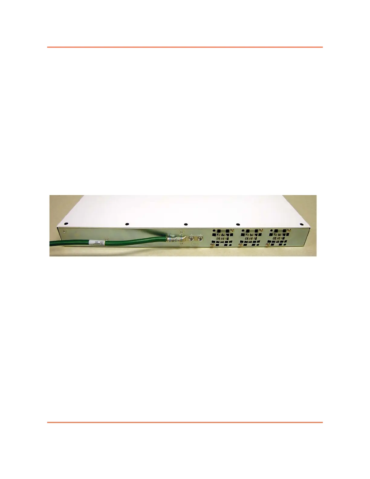
Figure 2-1
Installed Grounding Lug
You are required to provide the grounding lug and grounding wire. The
following description indicates the required specifications:
• #6 AWG (minimum) wire
• 2 hole lug @ 5/8” centers and with hole size for #10 or 1/4” screw
The ground source should be connected in accordance with local and national
regulations and safety guidelines, and the grounding procedures used by your
company.
The DC resistance between the chassis and the supplemental ground source
should be verified to be less than 100 milliohms.
Note: If your installation site allows rear access to the chassis, you can
install the supplemental ground connection after the chassis is mounted.
However, if you will not be able to access the rear of the unit after it is
mounted, you will need to install the supplemental ground connection
before mounting the chassis in the cabinet or frame.
See “Installing Supplemental Ground” on page 2-19 for a procedure.