8-6 Mounting Options
5160 Service Aggregation Switch Hardware Installation and Start-up Manual
009-3207-001 Standard Revision A
Copyright
©
2013 Ciena
®
Corporation September 2013
Procedure 8-1
Installing the Wallmount Bracket
Step Action
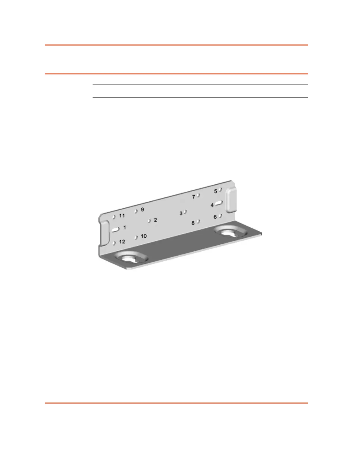
1 Align the holes of the mounting bracket with the holes on the left side of the
unit (see Figure 8-3) as follows:
• 3930, 3932, 3960, 5142, 5150 and 5160 — beginning with hole 3, install
screws in holes 3, 4 and 2.
• 3940 — beginning with hole 3, install screws in holes 3, 4, 2 and 1.
• 5140 — beginning with hole 3, install screws in holes 3, 4 and 1.
• 3920 — beginning with hole 5, install screws in holes 5, 6, 9 and 12.
Figure 8-3
Left Side Application
2 Align the holes of the mounting bracket with the holes on the right side of the
unit (see Figure 8-4 on page 8-7) as follows:
• 3930, 3932, 3960, 5142, 5150 and 5160 — beginning with hole 3, install
screws in holes 3, 4 and 2.
• 3940 — beginning with hole 3, install screws in holes 3, 4, 2 and 1.
• 5140 — beginning with hole 3, install screws in holes 3, 4 and 1.
• 3920 — beginning with hole 5, install screws in holes 5, 6, 9 and 12.