2-10 Installation
5160 Service Aggregation Switch Hardware Installation and Start-up Manual
009-3207-001 Standard Revision A
Copyright
©
2013 Ciena
®
Corporation September 2013
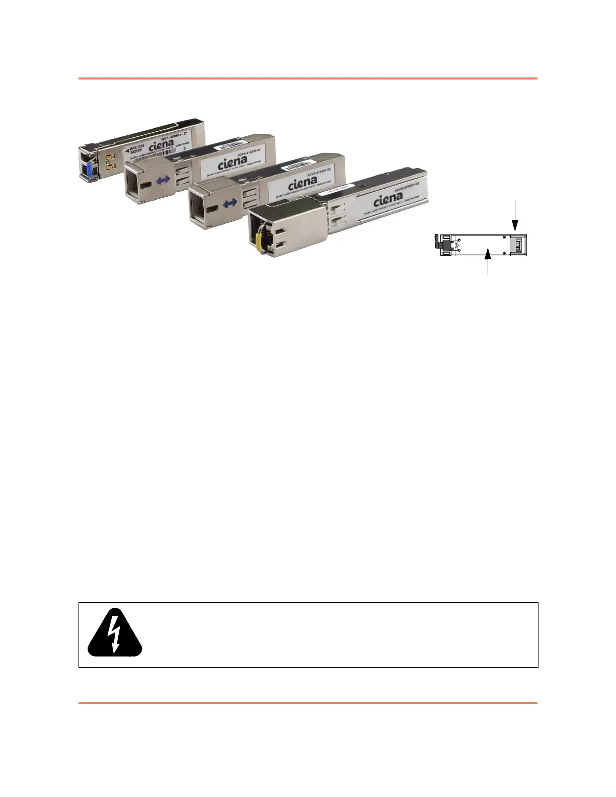
Figure 2-3
Pluggable Optic Modules
The installation procedure is the same for both SFP and SFP+ optics.
However, ensure that the installed optic matches the capability of the port and
that the optic is supported by the system. The list of supported SFPs is
documented in Packet Networking Transceivers Reference (009-2011-602).
Unsupported optics may not function.
Note: The top and bottom rows of SFP cages are oriented differently. If
the optic does not install easily, reorient the optic and try again.
Once installed, the port has LED indications. See “LED Overview” on page 5-1
for more information.
For additional information see:
• “To Install a Pluggable Optic” on page 2-27
• “To Remove a Pluggable Optic” on page 2-29
Cable Installation and Guidelines
This guide assumes that the site's data cables have been properly installed in
a centrally wired distribution configuration. When installing fiber optic cables
and other network cabling, always have them installed and tested by a
technician who is certified by the Electronics Industry Association/
Telecommunications Industry Association (EIA/TIA). This ensures a quality
installation and presents one less variable to consider when troubleshooting.
WARNING: All electrical connections are intended for indoor use only.
20-pin connector
Bottom of module