DOUT+
36R0
50mA
PTC
DIN
GND
PS3
GND
PS2
GND
PS1
PWR
A B PWR GND
MODULE PORT
IN+
IN-
GND
R-
B-
A+
Y+
GND
Y+
R-
THERMO-
COUPLE
PORT
RS485
PORT
ALARM
OUTPUT
DOUT-
DOUT+
AUXIO
GND
DOUT+
GND
OPN-G
GND
CLS-R
OPEN-G
GND
CLS-R
MAIN
VALVE
BATTERY-IN
GND
SOLAR
GND
PWR-OUT
BATTERY-OUT
PILOT
VALVE
POWER
PORT
DIGITAL
OUTPUTS
GND GND
GROUND
GND GND
DIGITAL
INPUTS
TRANS-
DUCER
PORT
11
1.3 Applicaon Informaon
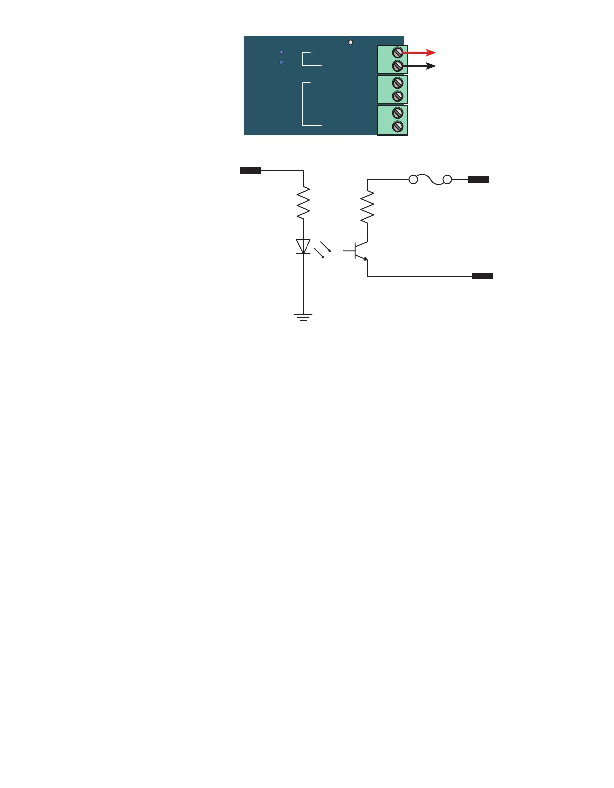
1.3.1 Alarm Output
The Alarm output indicates if the
system is in an abnormal state such as a
Shutdown or PILOT FAILURE. The output
behaves as a switch. By default, it is
closed when there is no alarm condion
but this can be changed in the IO
sengs. External alarm circuitry should
be limited to 50mA (Image 1.3.1).
OUT TO
AUTOMATION
PLC
Alarm output inacve/closed switch circuit diagram
Image 1.3.1 · Alarm output inacve