----- Supply network analyzer CVMk and CVMk-ITF ------ Page Nº 10
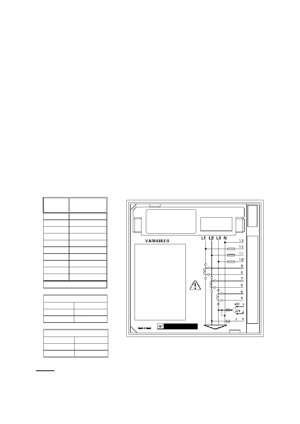
3.2. Connection terminal
The CVMk has a connection terminal located at the side of the instrument to
connect the power supply and the incoming network measuring signals.
This connection terminal consists of: Standard CVM model = 12 terminals
CVM - ITF model = 13 terminals*
Termn.
nr.
Parameter
13 * Neutral
12 VL1
11 VL2
10 VL3
9S1 IL1
8S2 IL1
7S1 IL2
6S2 IL2
5S1 IL3
4S2 IL3
Supply
CVMk....-
A.C. Supply
3 .... V
2 .... V
10 V
CVMk ....- / SDC
D.C. Supply
3
2 --
1 +d.c.
NOTE: Current inputs are isolated in the ... ITF ../5 A model