202
SVGm
Instruction Manual
ENGLISH
4
Figure 92: Change of cooling fans (Step 4).
Follow the steps from step 4 in section “10.5.-CHANGE OF COOLING FANS: SVGm type RACK”
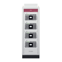
10.7.- CHANGE OF COOLING FANS: CABINET TYPE SVGm
Table 52: Tools needed (Cabinet type SVGm)
Tools needed
SVGm-3WF-100C, SVGm-4WF-069C and SVGm-4WF-067C:
1 Fan assembly replacement SVGm-xxx-100x, Code: 920124
SVGm-3WF-200C, SVGm-4WF-138C and SVGm-4WF-134C:
2 Fan assembly replacement SVGm-xxx-100x, Code: 920124
SVGm-3WF-300C, SVGm-4WF-207C and SVGm-4WF-201C:
3 Fan assembly replacement SVGm-xxx-100x, Code: 920124
SVGm-3WF-400C SVGm-4WF-276C and SVGm-4WF-268C:
4 Fan assembly replacement SVGm-xxx-100x, Code: 920124
25
Screwdriver for Torx 25 head screws
30
Screwdriver for Torx 30 head screws
4
Screwdriver for Allen 4 head screws
5
Screwdriver for Allen 5 head screws
10
Screwdriver for Hexagonal 10 mm head screws
To proceed to change the set of fans:
Place the SVGm in STOP mode and disconnect the device from the power. If necessary, disconnect
all the connection cables and short-circuit the current transformers.
Wait for 1 minute for the capacitors to discharge before opening the device.
Access the 100A modules through the front panel. This is done by loosening the front screws.
25 y 30 1.5 Nm
Proceed from point 3 of section “10.5.-CHANGE OF COOLING FANS: SVGm type RACK” with each of the
device’s 100A modules.
Note: When checking the fans in the “master” device, the slave device fans will be activated automat-
ically.
 Loading...