Do you have a question about the Circutor SVGm-4WF-020M-400 and is the answer not in the manual?
Critical warnings and precautions for safe operation, handling, and installation of the SVGm.
Procedures for checking the device upon receipt to ensure it meets specifications and is undamaged.
Guidelines for safe physical handling, loading, and unloading of the SVGm unit.
Introduction to the SVGm product line, detailing available models and power ratings.
Essential safety and procedural guidelines to follow before commencing SVGm installation.
Criteria for selecting an optimal and safe installation site for the SVGm unit.
Procedures for storing the SVGm for extended periods to maintain its condition and functionality.
Specific instructions for installing the wall-mounted SVGm units.
Procedures for installing the SVGm unit within a standard 19-inch rack cabinet.
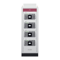
Steps for installing the SVGm unit in a free-standing cabinet configuration.
Guidelines and requirements for connecting the SVGm device to the power supply and network.
Detailed identification and description of all connection terminals on the SVGm device.
Visual representations of various wiring configurations for SVGm installation and measurement.
Instructions for connecting multiple SVGm units in parallel for increased capacity and redundancy.
Step-by-step guide for linking multiple SVGm units together for parallel operation.
Procedures for connecting multiple SVGm cabinets in a parallel operational setup.
Explanation of how the SVGm generates counter-phase current to compensate for reactive power.
How the SVGm compensates reactive current in medium voltage systems using transformers.
Option to monitor and control SVGm operation remotely using an external analyzer.
Setting up scheduled reactive power compensation targets based on time of day or week.
The device's built-in self-test system for checking hardware and software integrity.
Description of the SVGm's thermal protection levels, fan regulation, and safety shutdown features.
How the SVGm responds to low mains voltage conditions and the 'Low Vac' mode for continuous operation.
Enables faster response time for compensation in systems with rapid load changes, improving disturbance mitigation.
Description of the SVGm's TFT display, its layout, and information areas.
Information shown in the upper section of the SVGm display, including device status and maintenance indicators.
Content displayed in the central part of the SVGm screen, showing installation status, parameters, and graphs.
Navigation and configuration keys shown in the lower section of the SVGm display for user interaction.
Initial display shown after powering on the SVGm device, including master/slave status.
Detailed view of display screens for a single or master SVGm unit, including status and messages.
Display screen for a 'slave' SVGm device in a parallel configuration, showing its status.
Screens showing voltage, current, frequency, mains power, load power, and phasor measurements.
Screens for viewing active alarms and warnings, with details and management options.
Display of internal temperatures for inductors and IGBTs, indicating OK, High, or Low status.
How to access and navigate the device's configuration settings via the main screen.
Settings for language, device specifications, installed units, and operating limits.
Configuration of Cos Φ modes, reactive power offset, and voltage/reactive modes for compensation.
Setup for transformer, medium voltage, remote control, time programmer, Ethernet, RS-485, date/time, and password settings.
Wiring guidelines and limitations for establishing RS-485 communication between devices.
Details on the Modbus RTU protocol used by the SVGm for communication and data access.
Modbus memory map addresses for load and mains measurements like current, power, and Cos Φ.
Modbus map for static generator parameters such as temperatures, voltages, alarms, and status messages.
How to connect the SVGm via Ethernet for web server or Modbus/TCP communication.
Overview of recommended maintenance intervals and general procedures for the SVGm unit.
Detailed steps for performing standard preventive maintenance tasks on the SVGm.
Procedures for changing cooling fans across different SVGm models and types.
Maintenance and replacement procedures for surge protective devices and fuses in specific SVGm models.
Detailed electrical parameters including voltage, current, power, and frequency ratings for various models.
Physical characteristics, dimensions, operating conditions, protection degrees, and standards compliance.
Details on communication protocols and the types of fuses used in SVGm units.
Contact details for CIRCUTOR's Technical Support Service for operational queries or malfunctions.
| Brand | Circutor |
|---|---|
| Model | SVGm-4WF-020M-400 |
| Category | Portable Generator |
| Language | English |