B-8
Cisco 2600 Series Routers Hardware Installation Guide
OL-2171-02
Appendix B Maintaining the Router
Upgrading DRAM
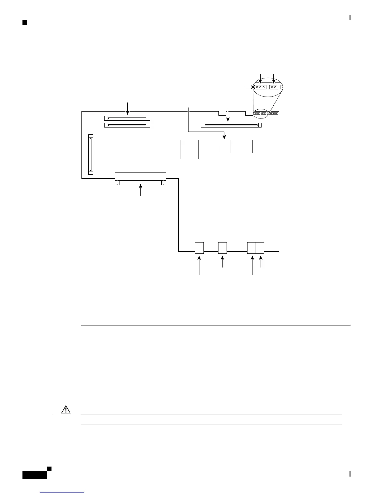
Figure B-5 DIMM Socket Location
DRAM DIMM Installation
To install the DRAM DIMMs:
Step 1 Power OFF the router.
Step 2 Attach an ESD-preventive wrist strap and ensure that it makes good contact with your skin. Connect the
equipment end of the wrist strap to the metal back plate of the chassis.
Step 3 Open the cover following the instructions in the “Removing the Chassis Cover” section on page B2.
Step 4 Begin removing the existing DRAM DIMM by pulling outward on the connectors to unlatch them, as
shown in step 1 of part A in Figure B-6. Be careful not to break the holders on the DIMM connector.
Step 5 Remove the existing DRAM DIMM by pulling the module straight up, as shown in step 2 of part A
inFigure B-6.
Caution To prevent damage, do not press on the center of the DIMMs. Handle each DIMM carefully.
Step 6 Position the new DIMM so that the polarization notch is located at the left end of the DIMM socket as
shown in Figure B-6.
56421
Ethernet
Console
AUX
Ethernet
Primary memory
(DRAM DIMMs)
Lattice
U22 U23
Advanced Interface
Module
PCI connector
System-code SIMM
(Flash memory)
Boot
ROM
Pin 1
Duart
reset
Reset
 Loading...