7-19
Cisco TelePresence System 3200
OL-14521-01
Chapter 7 Building the Second Row Table Assembly
Parts List
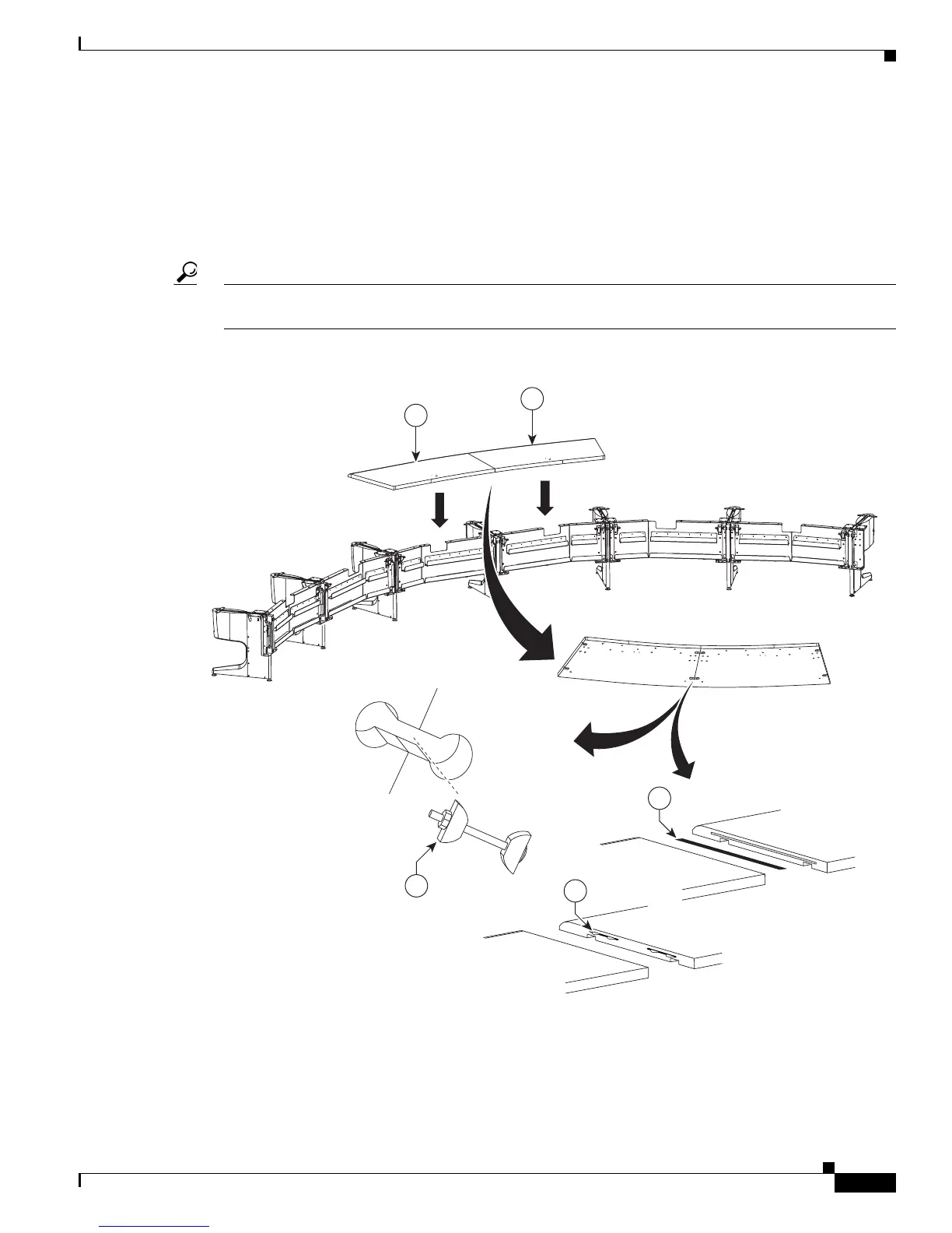
Step 17 Place the section 1 (section 5) and section 2 (section 4) tabletops on the table assembly; then use one of
the following methods to join the tabletops, depending on your attachment hardware:
• Insert the plastic spline in the slot between the two table sections and join the sections together, then
insert and tighten the draw bolts evenly on each side until the tabletop sections are joined.
• Insert four wooden biscuits in the slot between the two table sections and join the sections together,
then insert and tighten the draw bolts evenly on each side until the tabletop sections are joined.
Tip As you build the table tops, attempt to align the table feet with the table tops, and make sure that they
table tops are supported on at least three sides.
Figure 7-17 Tabletop Sections 1 and 2, Spline And Draw Bolts
Step 18 Place the Section 3 (section 6) tabletop on the table assembly; then use one of the following methods to
join the tabletops:
• Insert the plastic spline in the slot between the two table sections and join the sections together, then
insert and tighten the draw bolts evenly on each side until the tabletop sections are joined.