9-14
Cisco TelePresence System 3200
OL-14521-01
Chapter 9 Routing Power and Signal Cables
Power Requirements for the Cisco TelePresence 3200
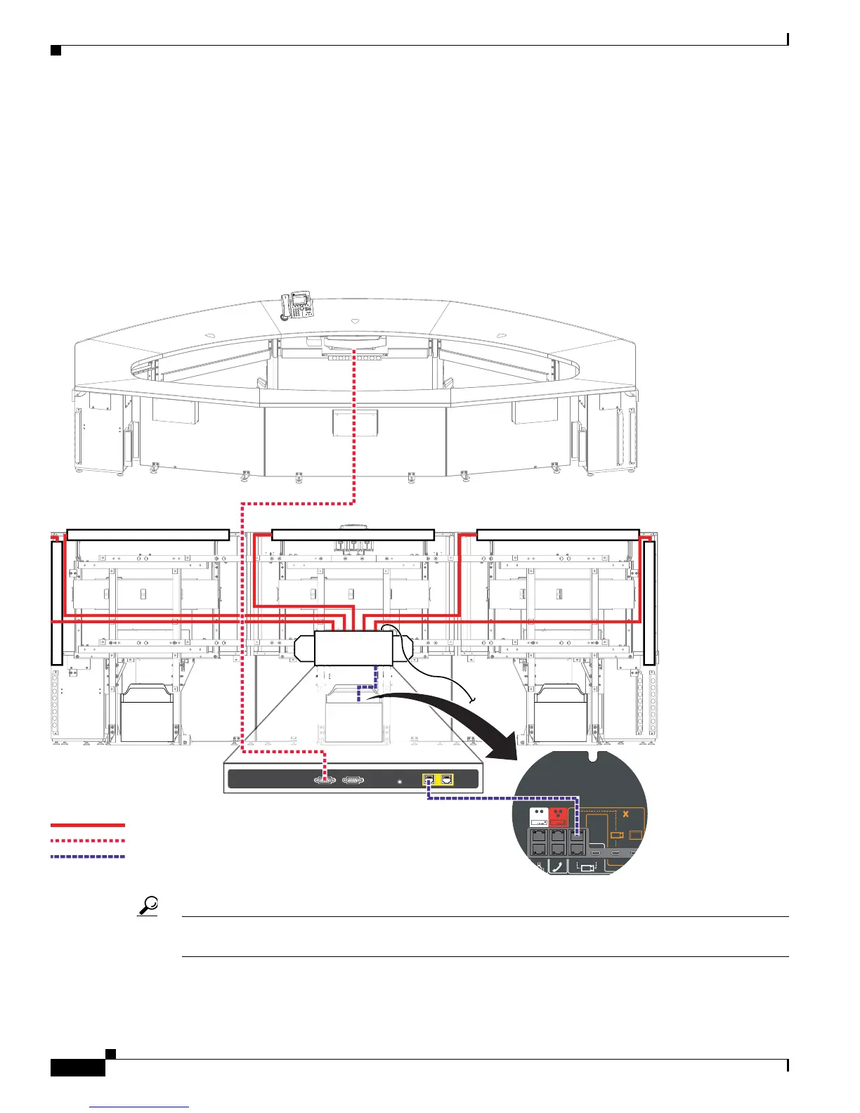
Step 11 Connect the following cables to the auxiliary control unit:
• Attach and route the power cables for the lighting assembly by connecting the lights to the auxiliary
control unit.
• Connect the DSUB to 8-P MINI DIN cable between the projector and the auxiliary control unit.
• Connect the Ethernet cables between the codec and the auxiliary control unit.
• Connect the power cord for the auxiliary control unit to a wall outlet.
Figure 9-11 Cabling the Lighting Assembly Power Cables and Auxiliary Control Unit-to-Projector Serial Cable
Tip Before plugging the Light fixture power cables into the unit, label each one. For example, 5’ Left light,
4’ Right light.
Primary Codec
12
12
10/100 NETWORK PO RTSRESETSERIAL PO RTS
TelePresence
3
DEF
6
MNO
9
WX
YZ
#
2
A
BC
5
JKL
8
TUV
0
OP
E
R
1
4
GHI
7
P
QRS
CIS
C
O
IP
P
HONE
7
97
0
Power
Projector
204158
RJ45 Ethernet
Auxiliary Control UnitAuxiliary Control UnitAuxiliary Control Unit