12-11
Cisco TelePresence System 3200
OL-14521-01
Chapter 12 Field-Replaceable Unit Guide
Replacing a Plasma Display—Part Number CTS-DISP-65-GEN4=
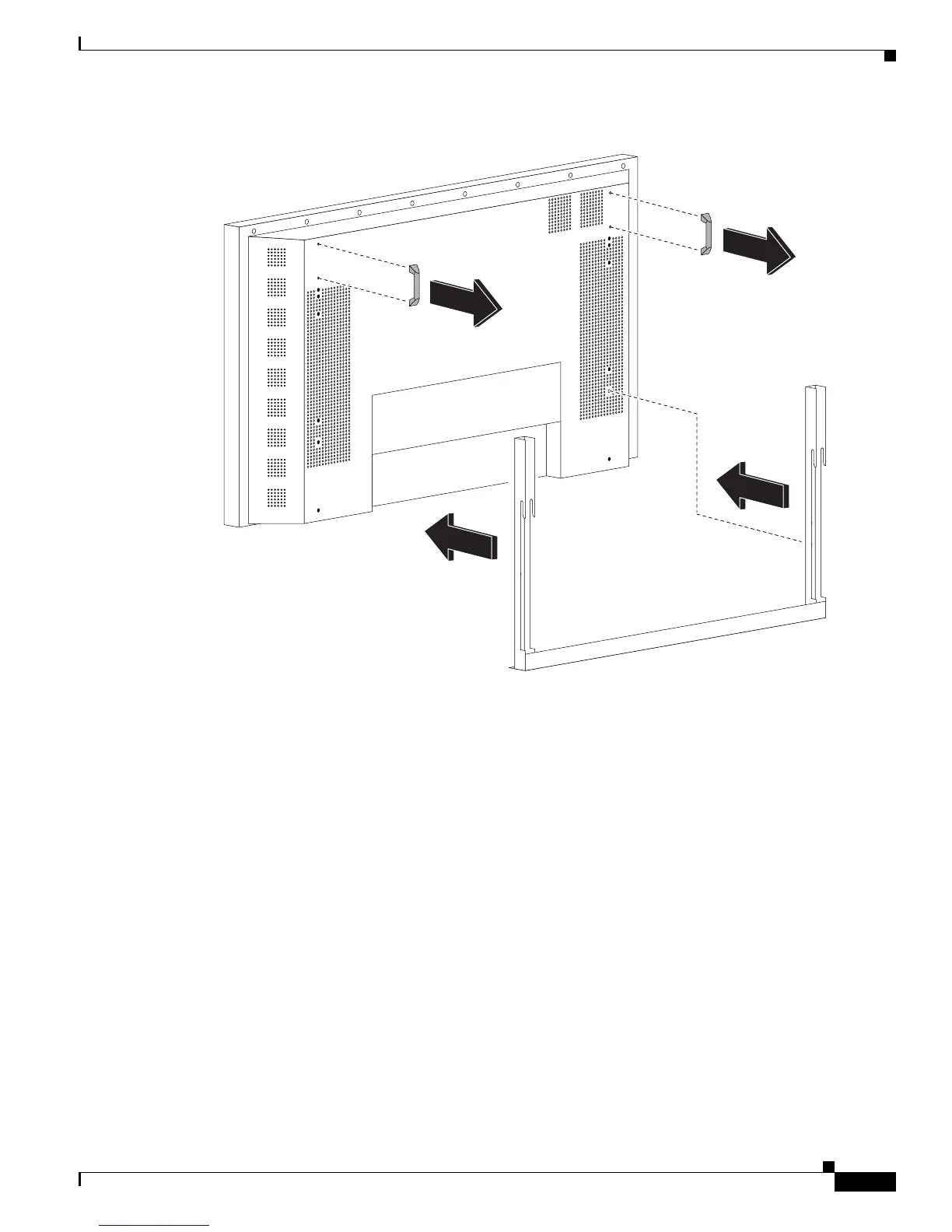
Figure 12-2 Attaching the Display Mounting Bracket
Step 10 Turn the power switch on the Plasma display to the On position.
Step 11 The rear of the replacement display will have either two HDMI connectors (see Figure 12-3) or two DVI
connectors (see Figure 12-4).
If the replacement display has two HDMI connectors, connect your existing signal cable to the codec
and to the left-most HDMI connector on the rear of the display (as viewed from the rear of the display),
as shown in Figure 12-3.
If the replacement display has two DVI connectors, connect the signal cable supplied with the
replacement display to the codec and to the left-most connector on the rear of the display (as viewed
from the rear of the display), as shown in Figure 12-4.
343309