2-10
Cisco TelePresence System 3200
OL-14521-01
Chapter 2 Building the Display Assembly
Parts List
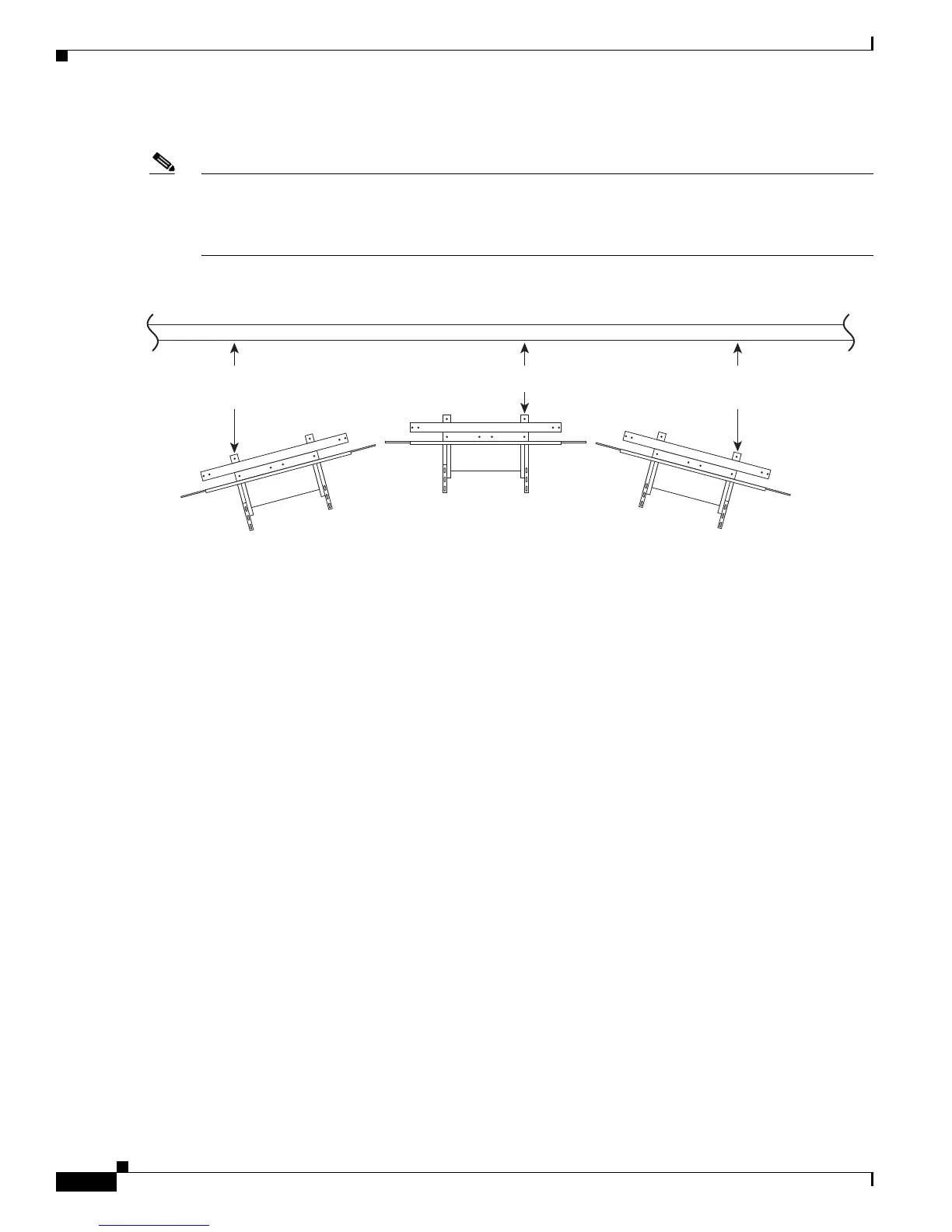
Step 9 Position the three Display structures relative to the rear wall.
Note Using the measurements provided in Figure 2-8, there will be approximately 3 inches (8 cm) of space
between the light reflector and the wall. These minimum dimensions can make installation of the light
reflector difficult. If your room size and room lighting pattern allow extra space, add extra space to these
minimum measurements.
Figure 2-8 Positioning the Display Structures
204152
Minimum 12 inches (30.5 cm)
Minimum 24 inches
(70 cm)
Minimum 24 inches
(70 cm)