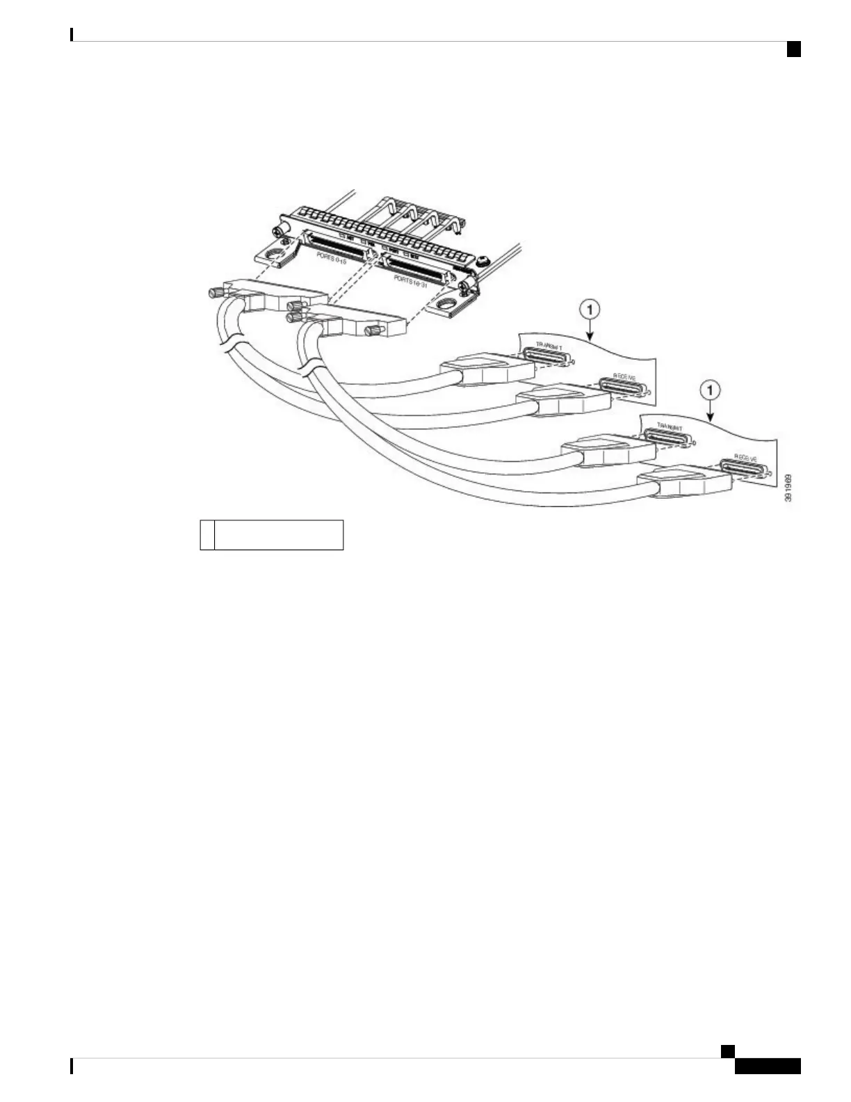
The figure below shows how the cable is connected between the 32 x T1/E1 interface module and the patch
panel.
Figure 63: Cable Installation between 32 x T1/E1 Interface and Patch Panel
Patch panel interfaces1
T1/E1 Pinouts
For information about the pinout of the cable connecting the T1/E1 interface to the rear of the patch panel,
see the T1/E1 Port Pinout .
RJ45 Cable Pinouts
T1 lines from individual subscribers are attached to RJ45 connectors on the front of the 24-port patch panel.
Each RJ45 port accommodates an individual T1 subscriber line.
For the T1/E1 ports, see the T1/E1 Port Pinout .
RJ48 Cable Pinouts
T1 lines from individual subscribers are attached to RJ45 connectors on the front of the 24-port patch panel.
Each RJ45 port accommodates an individual T1 subscriber line.
For the T1/E1 ports, see the T1/E1 Port Pinouts (RJ-48) section.
Connecting Cables to the Patch Panel
If you are connecting two T1/E1 interfaces to each other, you must cable both interfaces’ patch panels together
using a T1 cross-over cable or a T1 straight-through cable. Use shielded cables. The type of cable you use
(cross-over or straight-through) depends on how the T1/E1 interfaces are cabled to their patch panels:
• If both T1/E1 interfaces are connected to their patch panels in the same manner (TX to Transmit and RX
to Receive, or TX to Receive and RX to Transmit), use a T1 cross-over cable to connect the patch panels.
Cisco ASR 907 Router Hardware Installation Guide
109
Installing the Cisco ASR 907 Router
T1/E1 Pinouts