• If both T1/E1 interfaces are connected to their patch panels in a different configuration (TX to Transmit
and RX to Receive on one interface, and TX to Receive and RX to Transmit on the other interface), use
a T1 straight-through cable (standard RJ45 patch cable) to connect the patch panels.
To comply with the Telcordia GR-1089 NEBS standard for electromagnetic compatibility and safety, connect
the T1/E1 ports only to intra-building or unexposed wiring or cable. The intrabuilding cable must be shielded
and the shield must be grounded at both ends. The intra-building port(s) of the equipment or subassembly
must not be metallically connected to interfaces that connect to the OSP or its wiring. These interfaces are
designed for use as intra-building interfaces only (Type 2 or Type 4 ports as described in GR-1089-CORE)
and require isolation from the exposed OSP cabling. The addition of Primary Protectors is not sufficient
protection in order to connect these interfaces metallically to OSP wiring.
Warning
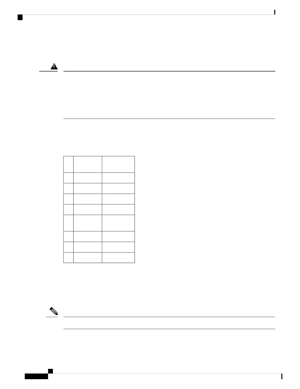
Patch Panel Pinout
Given below are the pinout information for the regular crossover and the straight-through cable patch panel.
Table 10: Pinout Details
Straight-throughCrossoverPin
#
Transmit TipReceive Tip1
Transmit RingReceive Ring2
——3
Receive TipTransmit Tip4
Receive RingTransmit
Ring
5
——6
——7
——8
Patch Panel Cabling for Redundancy
You can connect the patch panels with the interface modules for redundancy, using the Y-cables. The Y-cable
stub lengths are reduced, so that the cable does not exceed from the rack spacer. The Y-cables are numbered
based on the different stub length. Cable lengths differ for even numbered and odd numbered slots in the
chassis.
Do not try to interchange the cables as the length may vary based on odd and even slots.
Note
Cisco ASR 907 Router Hardware Installation Guide
110
Installing the Cisco ASR 907 Router
Patch Panel Pinout
 Loading...


