reach. Within the multimode category, only short reach is available. For information about optical SFP modules,
see the documentation for the SFP module at
http://www.cisco.com/en/US/partner/products/hw/modules/ps5455/prod_installation_guides_list.html.
LED Summary
The following sections describe the meanings of the LEDs on the Cisco ASR 907 Router.
RSP LEDs
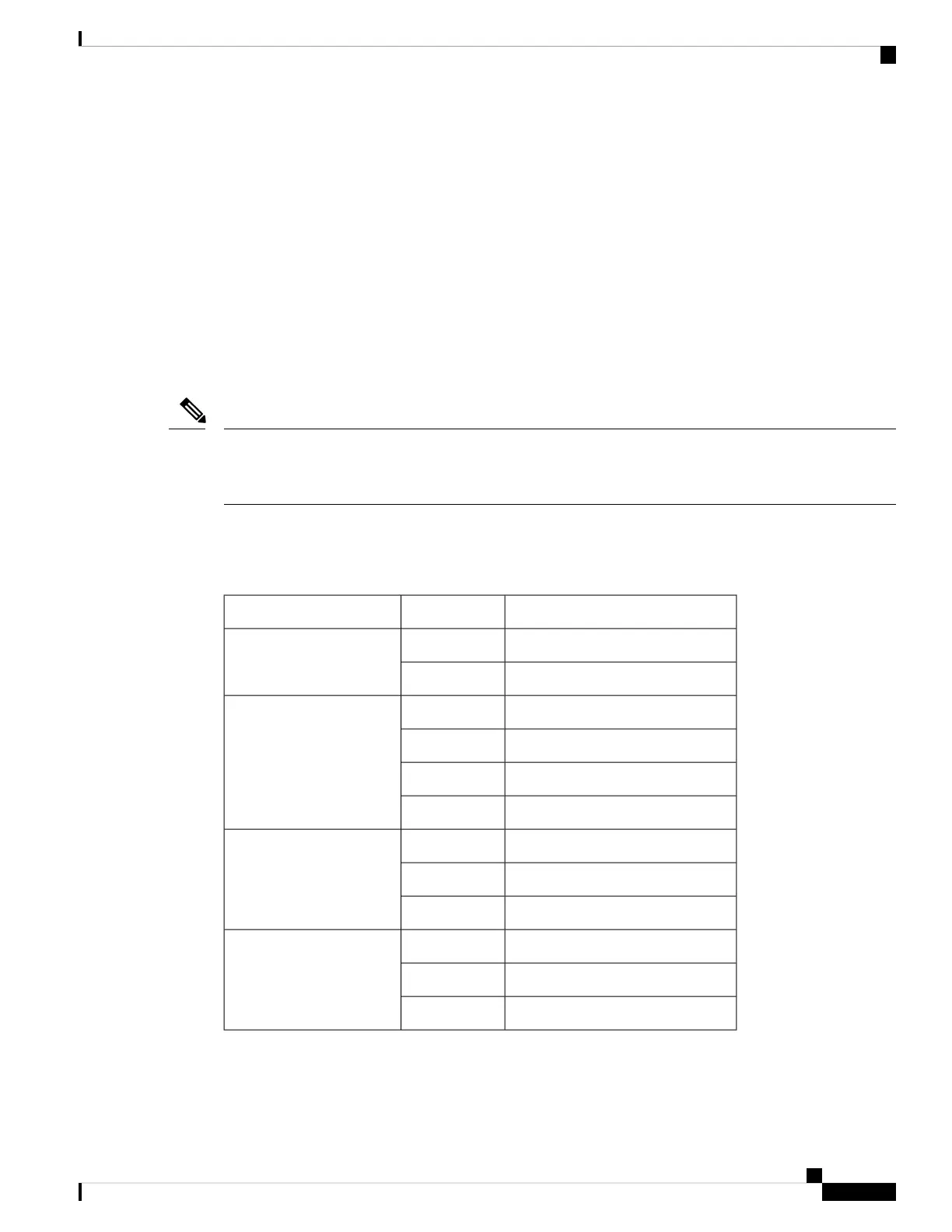
The table below summarizes the RSP LEDs.
A major alarm condition indicates the failure of a single fan in the fan tray; a critical alarm indicates the failure
of multiple fans. In the event that a single fan fails, the Cisco ASR 907 Router software adjusts the fan speed
to prevent excessive heat within the chassis.
Note
ASR900-RSP LED
Table 33: RSP LEDs
Description (two LEDs for each port)Color/StateLED
Disabled/no power to RSPOffPower (PWR)
Power rails on RSP in rangeGreen
Disabled/power down
OffStatus (STAT)
Failure to boot (lit at reset)Red
Rommon bootedYellow
IOS booted and runningGreen
Not available
OffActive (ACT)
Standby (indicates standby RSP)Yellow
Active (indicates active RSP)Green
No connection
OffManagement port (MGMT)
Connected with no activityGreen
Connected with activityFlashing green
Cisco ASR 907 Router Hardware Installation Guide
181
Troubleshooting
LED Summary