Use a 4-port EIA-232 DCE, 10 feet, Female DB-25, and CAB-HD4-232FC. Pinout of the DB25 connector
to be connected to the RS232-to-RS422 converter.
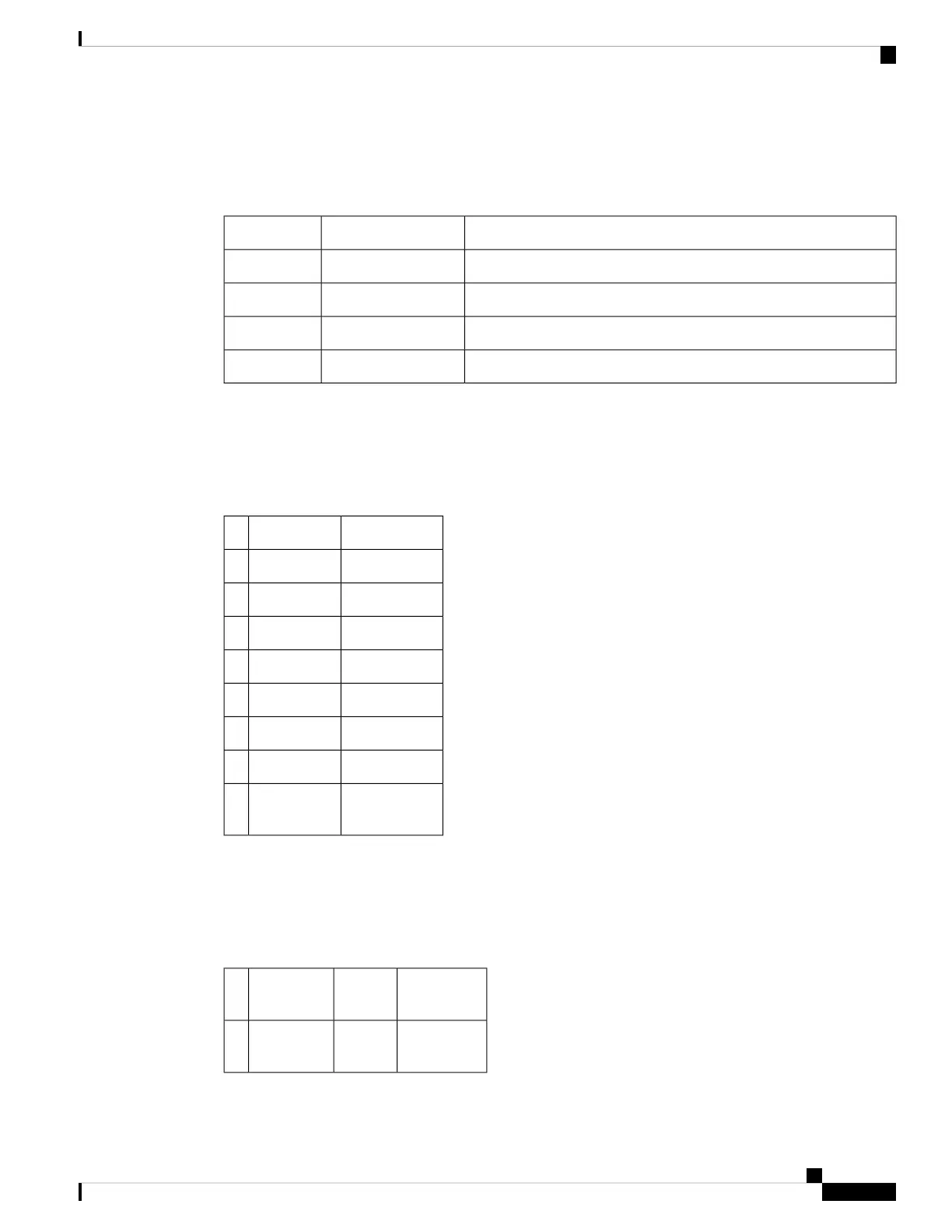
Table 17: RS422 Pinout
DescriptionSignal NamePin
RTS pin for RS232TXD+4
DTR pin for RS232TXD-20
CTS pin for RS232RXD+5
DSR pin for RS232RXD-6
Alarm Port Pinout
The table below summarizes the external alarm input pinout.
Table 18: External Alarm Input Pinout
DescriptionSignal NamePin
Alarm input 0ALARM0_IN1
Alarm input 1ALARM1_IN2
No connect3
Alarm input 2ALARM2_IN4
Alarm input 3ALARM3_IN5
No connect6
No connect7
Alarm
common
COMMON8
Console/Aux RJ45 RS232 Serial Port Pinout
The table below summarizes the console/aux RJ45 RS232 serial port pinout.
Table 19: Console/Aux RJ45 RS232 serial port
DescriptionDirectionSignal
Name
Pin
—Not
Used
RTS1
Cisco ASR 907 Router Hardware Installation Guide
159
Troubleshooting
Alarm Port Pinout
 Loading...


