Jack
Pin
Telco
RX
Signal NameBoard PinsJack PinTelco
TX
Signal NameBoard PInsLineBoard
Connector
4
28RX_RING_P3155128TX_RING_P3137Line 31
53RX_TIP_P312123TX_TIP_P313
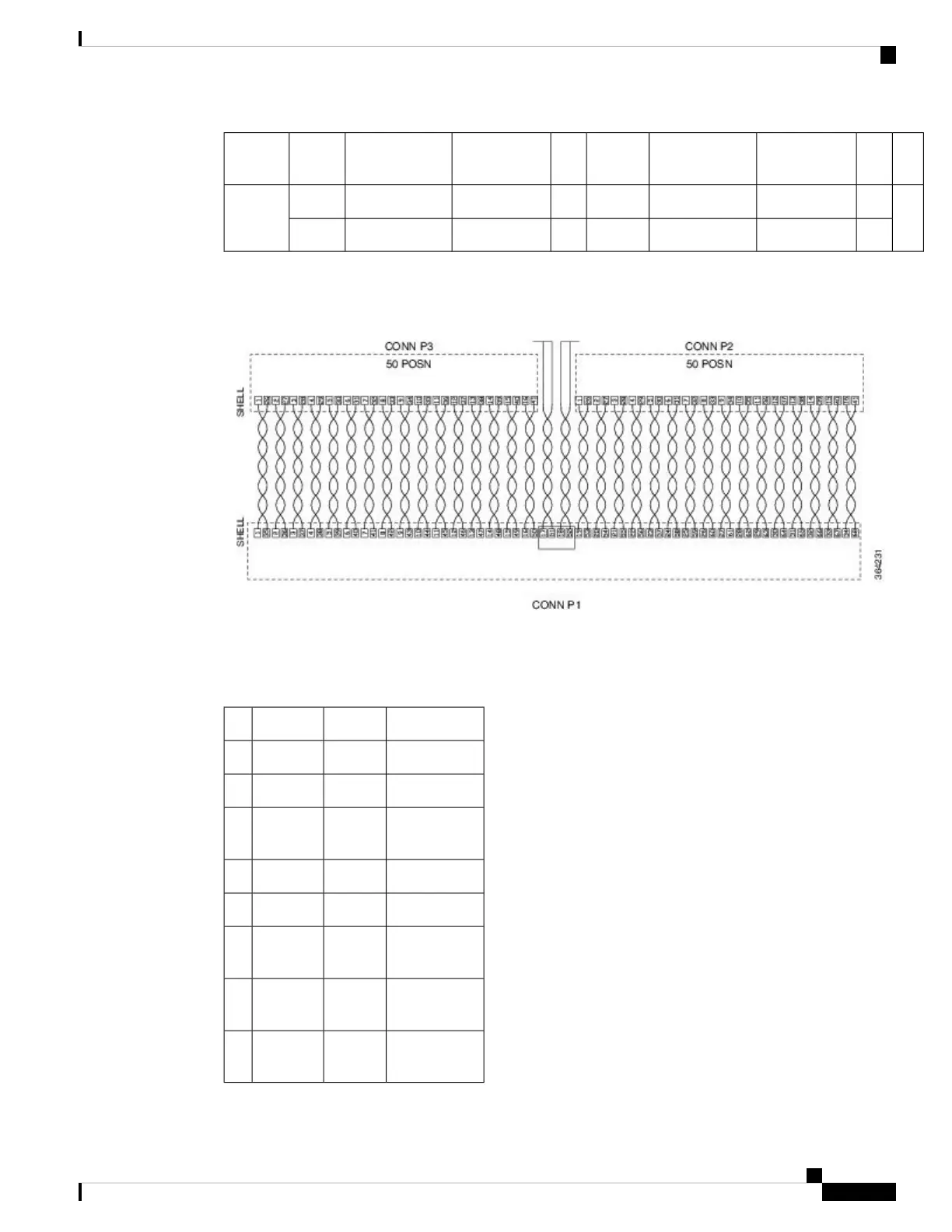
The figure below shows the wiring schematic of the cable used to connect the 32 T1/E1 interface module to
the rear of the patch panel.
Figure 99: 32 T1/E1 Wiring Schematic of Cable between 32 T1/E1 Interface and Patch Panel
8 T1/E1 Interface Module —RJ48C Port Pinnouts
Table 22: RJ48C Connector Pin-out for 8 T/E1 Interface Module
DescriptionDirectionSignalPin
Receive TipInputRX_TIP1
Receive RingOutputRX_RING2
Not
Connected
3
Receive TipInputTX_TIP4
Receive RingOutputTX_RING5
Not
Connected
6
Not
Connected
7
Not
Connected
8
Cisco ASR 907 Router Hardware Installation Guide
165
Troubleshooting
8 T1/E1 Interface Module —RJ48C Port Pinnouts