DescriptionDirectionSignal
Name
Pin
—Not
Used
DTR2
Transmit
data
OutputTXD3
—Not
Used
RI4
GND5
Receive dataInputRXD6
—Not
Used
DSR/DCD7
—Not
Used
CTS8
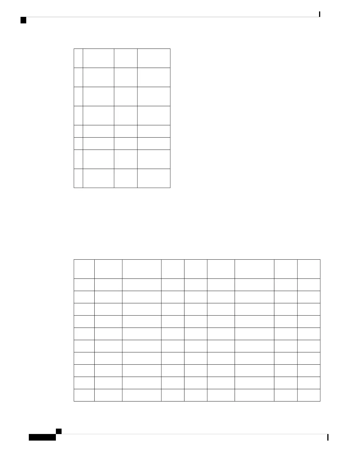
T1/E1 Port Pinout
16 T1/E1 Interface Module Pinout
The table below summarizes the pinouts of the cable (Tyco part number 2163442-1, Cisco part number
72-5184-01) used to connect the T1/E1 interface module to the rear of the patch panel.
Table 20: 16 T1/E1 Interface Pinouts
Jack PinTelco RXSignal NameBoard
Pins
Jack PinTelco TXSignal NameBoard PInsLine
439RX_RING_P192139TX_RING_P188Line 0
514RX_TIP_P142214TX_TIP_P138
438RX_RING_P291138TX_RING_P287Line 1
513RX_TIP_P241213TX_TIP_P237
435RX_RING_P380135TX_RING_P376Line 2
510RX_TIP_P330210TX_TIP_P326
434RX_RING_P479134TX_RING_P475Line 3
59RX_TIP_P42929TX_TIP_P425
441RX_RING_P594141TX_RING_P5100Line 4
516RX_TIP_P544216TX_TIP_P550
Cisco ASR 907 Router Hardware Installation Guide
160
Troubleshooting
T1/E1 Port Pinout