Home
Cisco
Network Router
ASR 907
Cisco ASR 907 User Manual
4
of 1
of 1 rating
204 pages
Give review
Manual
Specs
To Next Page
To Next Page
To Previous Page
To Previous Page
Loading...
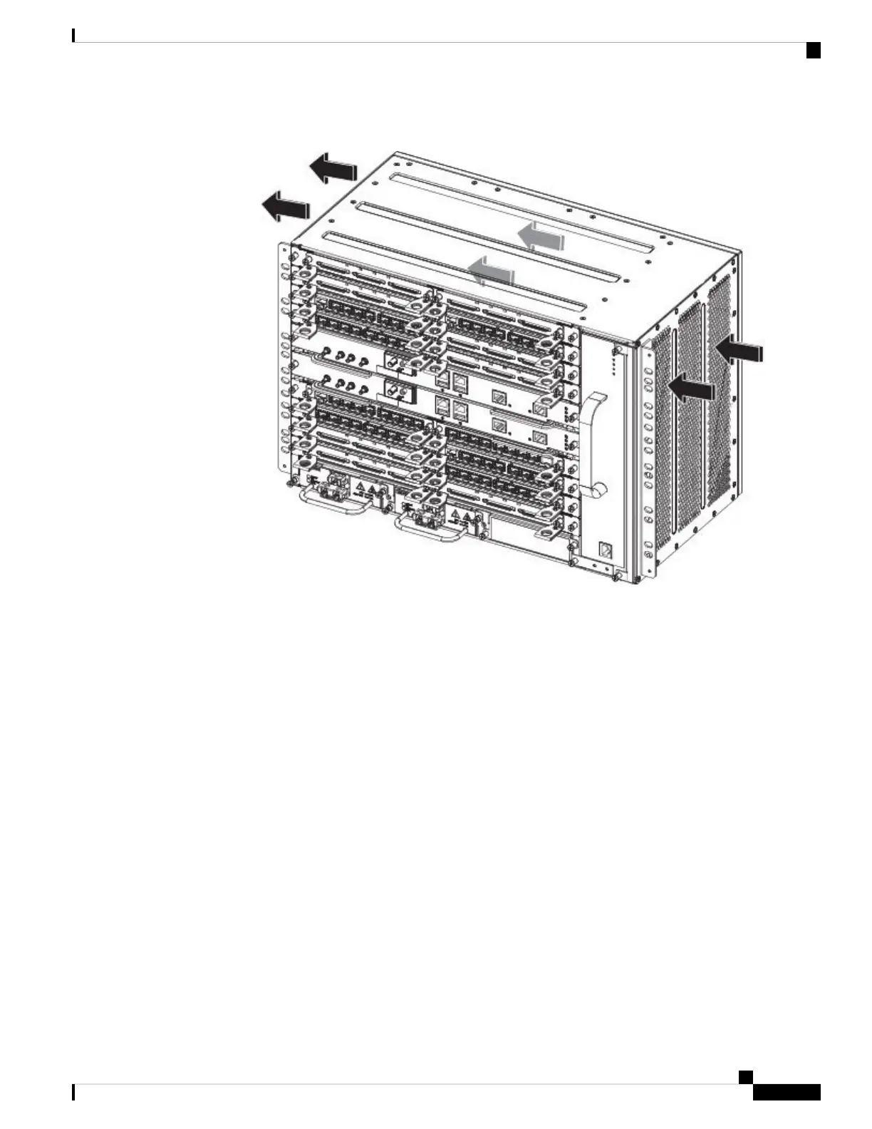
Figure
25:
Cisco
ASR
907
Router
Chassis
Air
Flow
T
o
ensure
adequate
airflow
,
it
is
recommended
that
you
maintain
a
minimum
clearance
distance
always,
as
mentioned
in
the
following
figure.
Cisco
ASR
907
Router
Hardware
Installation
Guide
41
Preparing
for
Installation
Air
Flow
Guidelines
50
52
Table of Contents
Default Chapter
4
Table of Contents
4
(A900-Ima8T1Z)
27
2-Port 10 Gigabit Ethernet SFP+ Interface Module (A900-IMA2Z)
28
1-Port 100 Gigabit Ethernet Interface Module (1X100Ge) (A900-IMA1C)
29
2-Port 100 Gigabit Ethernet Interface Module (2X100GE) (N560-IMA2C)
29
2-Port 40 Gigabit Ethernet QSFP Interface Module (2X40Ge) (A900-IMA2F)
30
Ethernet (CSFP) Interface Module (A900-IMA8CS1Z-M)
30
16-Port T1/E1 Interface Module (A900-IMA16D)
31
32-Port T1/E1 Interface Module (A900-IMA32D)
32
8-Port T1/E1 Interface Module (A900-IMA8D)
33
48-Port T1/E1 CEM Interface Module (A900-IMA48D-C)
33
48-Port T3/E3 CEM Interface Module (A900-IMA48T-C)
34
1-Port OC-48/STM-16 or 4-Port OC-12/OC-3 / STM-1/STM-4 + 12-Port T1/E1 + 4-Port
35
CEM Interface Module (A900-IMA3G-IMSG)
35
(A900-Ima8S1Z-CX)
35
(A900-Ima1Z8S-Cxms)
37
Temperature Sensor
39
Interface Numbering
39
Regulatory Compliance
39
CHAPTER 2 Preparing for Installation
41
Safety Guidelines
41
Standard Warning Statements
41
Safety Guidelines for Personal Safety and Equipment Protection
43
Safety Precautions for Module Installation and Removal
43
Safety with Electricity
44
Power Supply Considerations
48
Preventing ESD Damage
48
Site Planning
49
General Precautions
49
Site Planning Checklist
49
Site Selection Guidelines
49
Environmental Requirements
50
Physical Characteristics
50
Assembly Guidelines
50
Air Flow Guidelines
50
Air Flow Guidelines for Enclosed Rack Installation
54
Floor Loading Considerations
54
Site Power Guidelines
54
Electrical Circuit Requirements
56
Site Cabling Guidelines
56
Asynchronous Terminal Connections
57
Interference Considerations
57
Rack-Mounting Guidelines
57
Precautions for Rack-Mounting
58
Rack Selection Guidelines
58
Equipment Rack Guidelines
58
Installation Checklist
59
Creating a Site Log
60
Receiving the Cisco ASR 907 Router
60
Chassis-Lifting Guidelines
61
Tools and Equipment
62
Unpacking and Verifying the Shipped Contents
63
CHAPTER 3 Installing the Cisco ASR 907 Router
65
Prerequisites
65
Installing the Router in a Rack
65
Installing the Chassis Brackets
65
Installing the Router Chassis in the Rack
66
Installing Plenum A907-F2B-AIR-U Assembly and Chassis in the Rack
69
Installing the Chassis in the Air Plenum
74
Attaching the Cable Management Brackets
75
Installing the Chassis Ground Connection
76
Installing the Fan Tray
79
Removing and Replacing the Dust Filter
80
Removing the Dust Filter
81
Dust Filter Maintenance
81
Removing and Replacing the Fan Tray
82
RSP Installation
84
Installing an RSP Module
84
Removing an RSP Module
86
Hot-Swapping an RSP Module
87
Installing the Interface Module Carrier
88
Interface Module Installation
88
Installing an Interface Module
89
Removing an Interface Module
90
Hot-Swapping an Interface Module
90
Installing the Power Supply
92
Preventing Power Loss
93
Power Connection Guidelines
93
Guidelines for DC-Powered Systems
94
Guidelines for AC-Powered Systems
94
Installing the DC Power Supply
94
Installing the DC Power Supply Module
94
Connecting DC Power Supply Unit (A900-PWR900-D2)
95
Activating the DC Power Supply
97
Removing and Replacing the DC Power Supply
98
Installing the AC Power Supply
99
Installing the AC Power Supply Module for A900-PWR1200-A (1200 W)
99
Recommended Power Cables
100
Activating the AC Power Supply
101
Removing and Replacing the AC Power Supply
101
Installing Dust Caps
102
Connecting the Cisco ASR 907 Router to the Network
103
Connecting Console Cables
103
Connecting to the Serial Port Using Microsoft Windows
103
Connecting to the Console Port Using Mac os X
106
Connecting to the Console Port Using Linux
106
Installing the Cisco Microsoft Windows USB Device Driver
107
Uninstalling the Cisco Microsoft Windows USB Driver
108
Connecting to the Auxiliary Port
109
Connecting a Management Ethernet Cable
111
Installing and Removing SFP and XFP Modules
111
Connecting a USB Flash Device
111
Removing a USB Flash Device
112
Connecting Timing Cables
112
Connecting Cables to the BITS Interface
112
Connecting Cables to a GNSS Interface
113
Connecting a Cable to the GNSS Antenna Interface
114
Connecting Ethernet Cables
115
Connecting Cables to SFP Modules
116
Connecting T1/E1 Cables
116
Installing the Cable Connectors
116
T1/E1 Pinouts
119
RJ45 Cable Pinouts
119
RJ48 Cable Pinouts
119
Connecting Cables to the Patch Panel
119
Patch Panel Pinout
120
Patch Panel Cabling for Redundancy
120
Recommended Patch Panel
122
Installing Patch Panel
123
Install 3G Patch Panel
127
Install Rack Brackets
128
Set up 3G Patch Panel on Rack
135
Wall Mount 3G Patch Panel
147
Patch Panel Dimensions
149
Connecting Serial Cables
154
Connecting the Fan Tray Alarm Port
155
Connector and Cable Specifications
156
CHAPTER 4 Cisco Router Initial Configuration
157
Checking Conditions Prior to System Startup
157
Powering up the Cisco ASR 907 Router
158
Verifying the Front Panel Leds
160
Verifying the Hardware Configuration
161
Checking Hardware and Software Compatibility
161
Configuring the Cisco ASR 907 Router at Startup
161
Using the Console Interface
161
Configuring Global Parameters
162
Checking the Running Configuration Settings
163
Saving the Running Configuration to NVRAM
164
Safely Powering off the Cisco ASR 907 Router
164
CHAPTER 5 Troubleshooting
167
Pinouts
167
BITS Port Pinout
167
GPS Port Pinout
168
Time of Day Pinout
168
Alarm Port Pinout
169
Console/Aux RJ45 RS232 Serial Port Pinout
169
T1/E1 Port Pinout
170
T1/E1 Interface Module Pinout
170
T1/E1 Interface Module Pinout
172
T1/E1 Interface Module RJ48C Port Pinnouts
175
AMP64 Pinouts
176
Patch Panel Pinout
181
Serial Cable Pinouts
186
DB-9 Connector Pinouts
186
RJ-45 Connector Pinouts
187
Connector Pinouts
188
Management Ethernet Port Pinout
189
USB Console Port Pinout
189
USB Flash/Mem Port Pinout
190
Fiber-Optic Specifications
190
LED Summary
191
RSP Leds
191
Asr900-Rsp Led
191
ASR900-RSP3C-400-W LED Fault Condition
192
Interface Module Leds
193
1-Port OC-192 or 8-Port Low Rate CEM Interface Module Leds
194
48 T1/E1 and 48 T3/E3 Interface Module Leds
195
OC-3 Interface Module Leds
196
T1/E1 Interface Module Leds
196
Serial Interface Module Leds
199
Power Supply Leds
199
Fan Tray Leds
200
Alarm Conditions
201
Appendix A Site Log and Manufactures
203
Manufactures
204
Other manuals for Cisco ASR 907
Installing
92 pages
4
Based on 1 rating
Ask a question
Give review
Questions and Answers:
Need help?
Do you have a question about the Cisco ASR 907 and is the answer not in the manual?
Ask a question
Cisco ASR 907 Specifications
General
Brand
Cisco
Model
ASR 907
Category
Network Router
Language
English
Related product manuals
Cisco ASR 903
28 pages
Cisco ASR 901
218 pages
Cisco ASR 9000
188 pages
Cisco ASR 9001
44 pages
Cisco ASR 9010
44 pages
Cisco ASR 9006
44 pages
Cisco ASR 9000v
284 pages
Cisco ASR 9001-S
170 pages
Cisco ASR 900 Series
174 pages
Cisco ASR 9000 Serie
378 pages
Cisco ASR 9000 Series
422 pages
Cisco ASR 920 series
36 pages