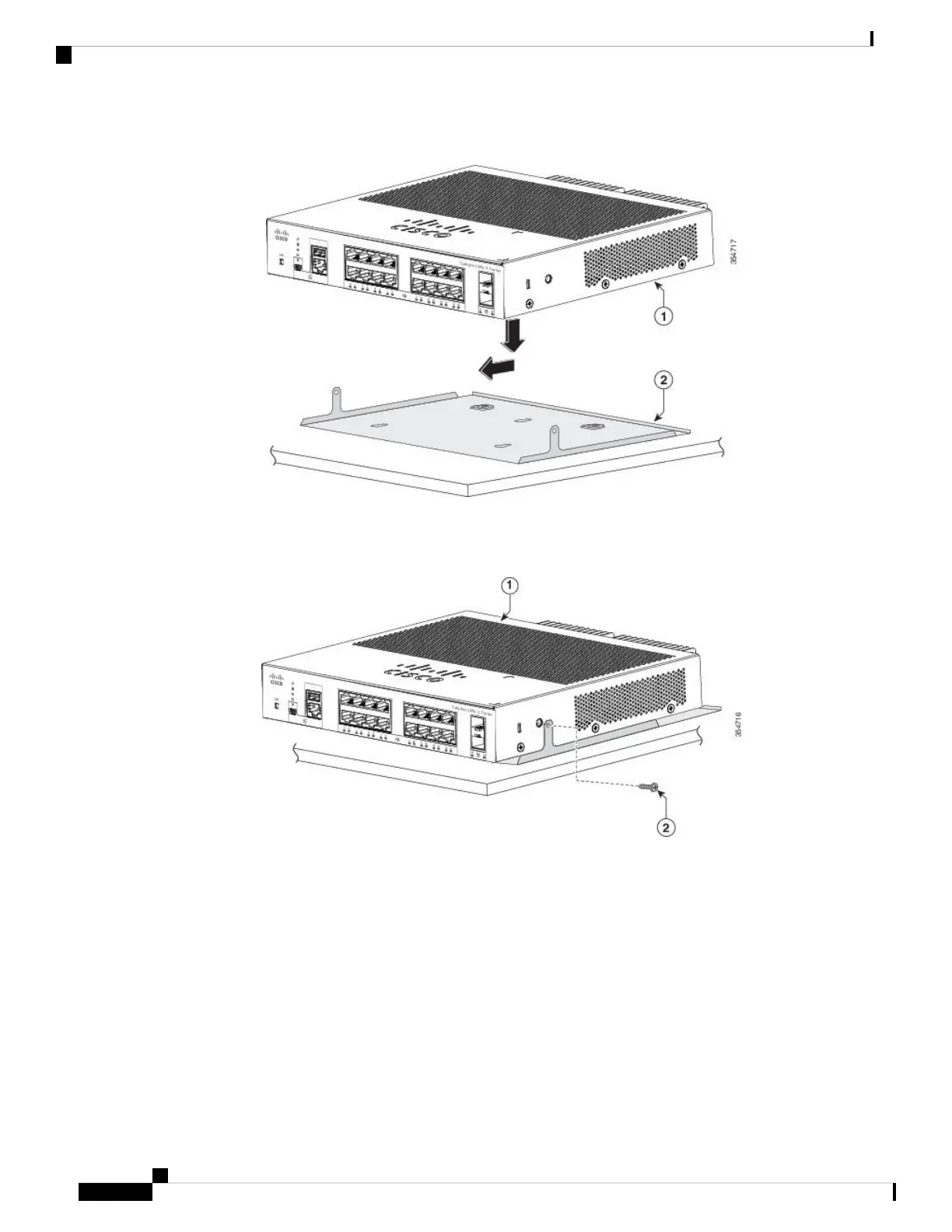
Figure 18: Placing the Switch on the Mounting Tray
Step 2 Use the two number-10 Phillips pan-head screws to secure the mounting tray to the switch.
Figure 19: Securing the Mounting Tray to the Switch
Step 3 Place one side of the magnet against the bottom of the mounting tray. Mount the magnet and switch on a metal wall.
Read the wall-mounting instructions carefully before beginning installation. Failure to use the correct hardware
or to follow the correct procedures could result in a hazardous situation to people and damage to the system.
Statement 378
Warning
Do not wall-mount the switch with its front panel facing up. Following safety regulations, wall-mount the
switch with its front panel facing down or to the side, to allow sufficient airflow and to provide easier access
to the cables.
Caution
Cisco Catalyst 2960-L Series 8-Port and 16-Port Switch Hardware Installation Guide
26
Switch Installation
Mounting Tray with a Magnet

 Loading...


