EasyManuals Logo

Cisco Catalyst 2960-L Series User Manual

Cisco Catalyst 2960-L Series
80 pages
To Next Page IconTo Next Page
To Previous Page IconTo Previous Page
Page #35 background imageLoading...
Page #35 background image
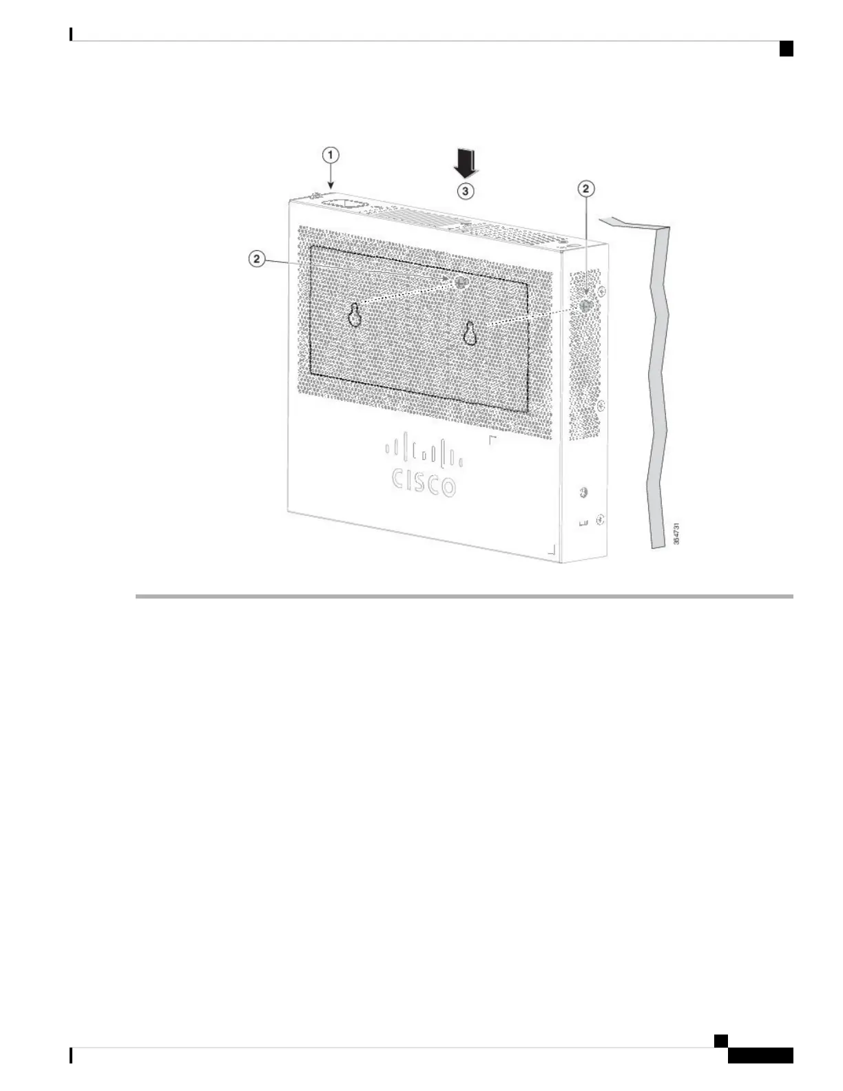
Figure 14: Installing the Switch on a Wall
With a Mounting Tray
The mounting kit (part number CMPCT-MGNT-TRAY=) is optional. You can order it when you order your
switch, or you can order it later from your Cisco representative.
The mounting kit ships contents:
Two number-10 Phillips pan-head screws
Three number-8 Phillips pan-head screws
Mounting tray
Magnet
You can use the mounting tray by itself with mounting screws, or with a magnet.
Mounting Tray with Screws
You can use the mounting tray to secure the switch:
On a desk or shelf
Under a desk or shelf
Cisco Catalyst 2960-L Series 8-Port and 16-Port Switch Hardware Installation Guide
23
Switch Installation
With a Mounting Tray

Table of Contents

Questions and Answers:

Question and Answer IconNeed help?

Do you have a question about the Cisco Catalyst 2960-L Series and is the answer not in the manual?

Cisco Catalyst 2960-L Series Specifications

General IconGeneral
SeriesCatalyst 2960-L
Ports8, 16, 24, or 48 Gigabit Ethernet ports
LayerLayer 2
Flash Memory64 MB
MAC Address Table Size8, 000 entries
Uplink2 or 4 Gigabit SFP
PoEAvailable on selected models
VLAN SupportUp to 255 VLANs
Power SupplyInternal power supply
Operating Temperature0°C to 40°C (32°F to 104°F)
Dimensions44.5 x 27.9 x 4.45 cm (17.5 x 11.0 x 1.75 in.)

Related product manuals