EasyManuals Logo

Cisco Catalyst 2960-L Series User Manual

Cisco Catalyst 2960-L Series
80 pages
To Next Page IconTo Next Page
To Previous Page IconTo Previous Page
Page #37 background imageLoading...
Page #37 background image
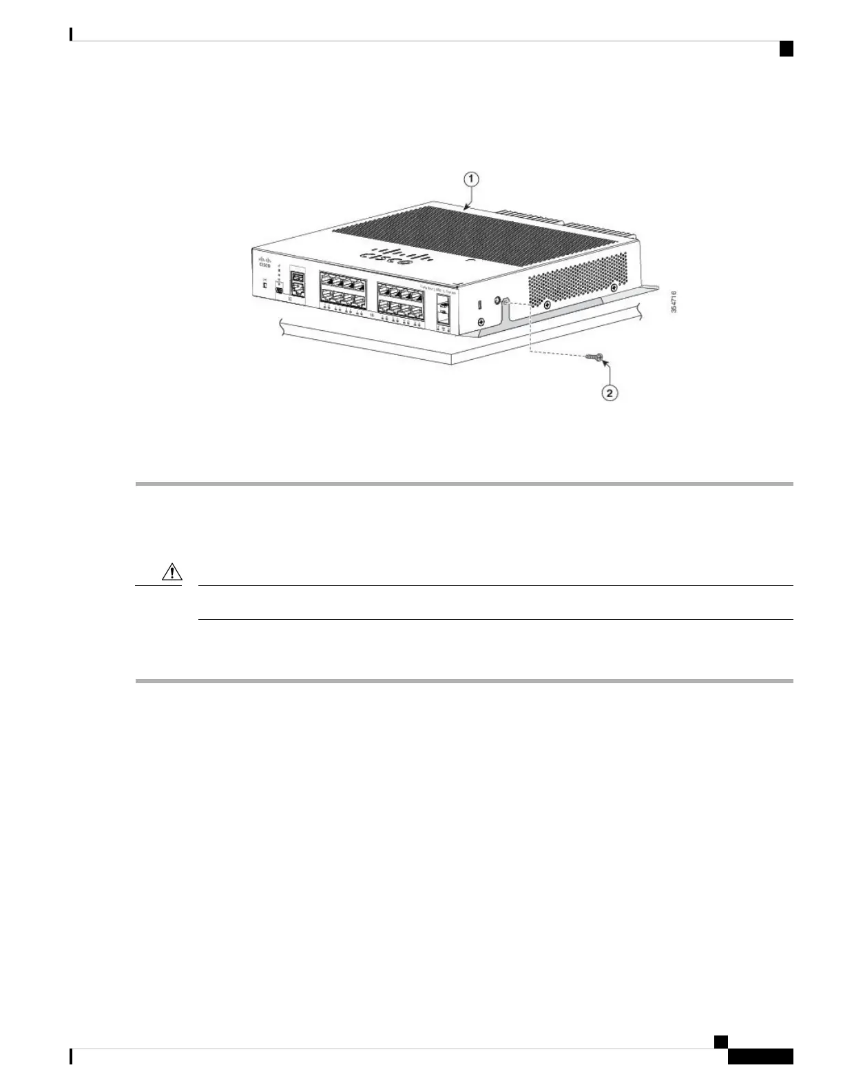
Step 5 Use the two number-10 Phillips pan-head screws to secure the switch to the mounting tray.
Figure 17: Securing the Switch to the Mounting Tray
To prevent airflow restriction, allow clearance around the ventilation openings to be at least: 3 in. (7.6 cm)
Statement 1076
Warning
Mounting Tray with a Magnet
You can use a magnet with the mounting tray to mount the switch on a metal surface.
Do not use the magnet without a mounting tray
Caution
This example shows you how to mount the switch on a metal wall. You can use a similar procedure to mount
the switch on, or under, a metal desk.
Step 1 Place the switch on the mounting tray.
Cisco Catalyst 2960-L Series 8-Port and 16-Port Switch Hardware Installation Guide
25
Switch Installation
Mounting Tray with a Magnet

Table of Contents

Questions and Answers:

Question and Answer IconNeed help?

Do you have a question about the Cisco Catalyst 2960-L Series and is the answer not in the manual?

Cisco Catalyst 2960-L Series Specifications

General IconGeneral
SeriesCatalyst 2960-L
Ports8, 16, 24, or 48 Gigabit Ethernet ports
LayerLayer 2
Flash Memory64 MB
MAC Address Table Size8, 000 entries
Uplink2 or 4 Gigabit SFP
PoEAvailable on selected models
VLAN SupportUp to 255 VLANs
Power SupplyInternal power supply
Operating Temperature0°C to 40°C (32°F to 104°F)
Dimensions44.5 x 27.9 x 4.45 cm (17.5 x 11.0 x 1.75 in.)

Related product manuals