EasyManuals Logo

Cisco Catalyst 2960-L Series User Manual

Cisco Catalyst 2960-L Series
80 pages
To Next Page IconTo Next Page
To Previous Page IconTo Previous Page
Page #43 background imageLoading...
Page #43 background image
To prevent airflow restriction, allow clearance around the ventilation openings to be at least: 3 in. (7.6 cm)
Statement 1076
Warning
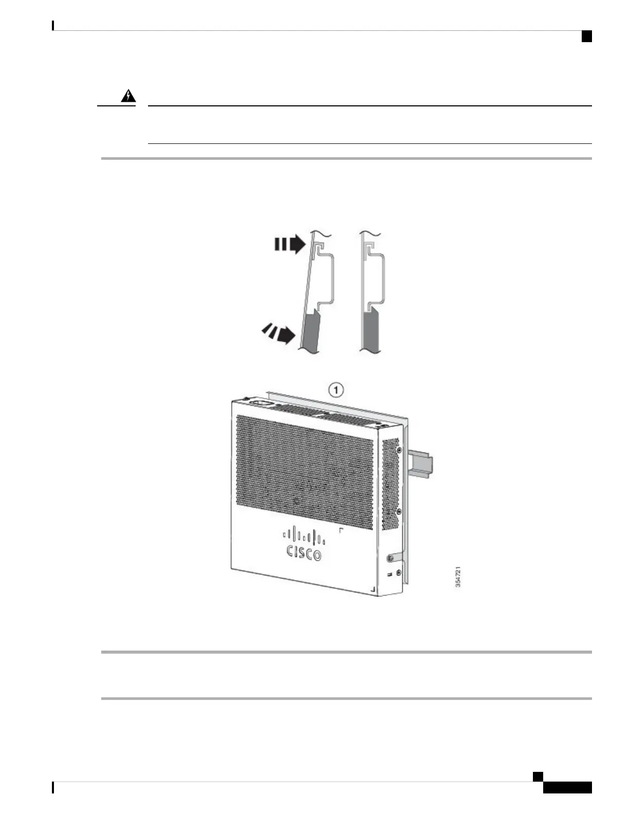
Step 1 Position the switch directly in front of the DIN rail, making sure that the top of the DIN rail mount clip hooks over the
top of the DIN rail.
Figure 25: Mounting the Switch on a DIN Rail
Step 2 Rotate the switch down toward the DIN rail until the release tabs on the DIN rail mount clicks.
Step 3 Lift lightly on the bottom of the switch to ensure that it is firmly locked in place.
Removing the Switch from a DIN Rail
Step 1 Ensure that power is removed from the switch, and disconnect all cables and connectors from the front panel of the switch.
Cisco Catalyst 2960-L Series 8-Port and 16-Port Switch Hardware Installation Guide
31
Switch Installation
Removing the Switch from a DIN Rail

Table of Contents

Questions and Answers:

Question and Answer IconNeed help?

Do you have a question about the Cisco Catalyst 2960-L Series and is the answer not in the manual?

Cisco Catalyst 2960-L Series Specifications

General IconGeneral
SeriesCatalyst 2960-L
Ports8, 16, 24, or 48 Gigabit Ethernet ports
LayerLayer 2
Flash Memory64 MB
MAC Address Table Size8, 000 entries
Uplink2 or 4 Gigabit SFP
PoEAvailable on selected models
VLAN SupportUp to 255 VLANs
Power SupplyInternal power supply
Operating Temperature0°C to 40°C (32°F to 104°F)
Dimensions44.5 x 27.9 x 4.45 cm (17.5 x 11.0 x 1.75 in.)

Related product manuals