B-56
Cisco IE 3000 Switch Hardware Installation Guide
OL-13017-01
Appendix B Installation In a Hazardous Environment
Connecting the Switch to the Power Converter
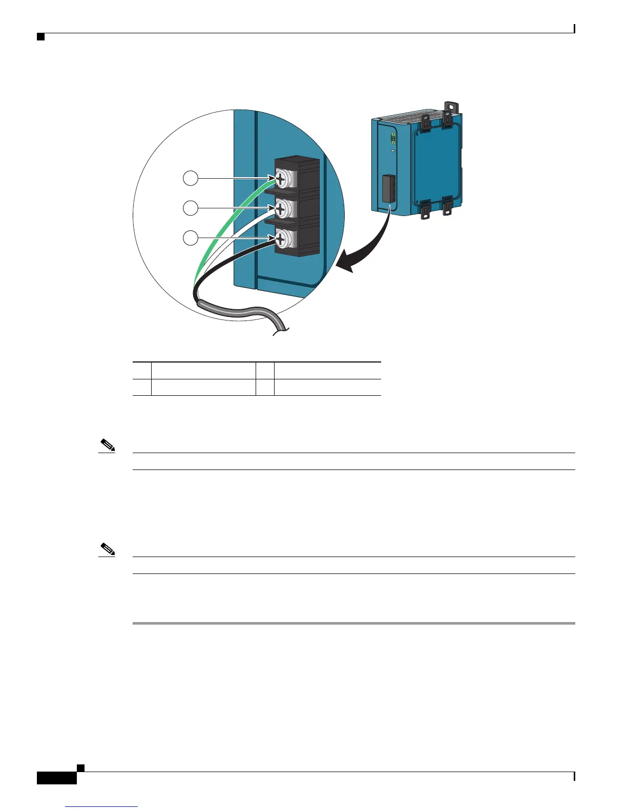
Figure B-44 Connecting AC Power to the Power Converter
Step 3 Tighten the ground wire terminal block screw.
Note The torque should not exceed 10 in-lb.
Step 4 Insert the line and neutral wire leads into the terminal block line and neutral connections. See
Figure B-44. Make sure that you cannot see any wire lead. Ensure that only wire with insulation extends
from the connectors.
Step 5 Tighten the line and neutral terminal block screws.
Note The torque should not exceed 10 in-lb.
Step 6 Replace the plastic cover over the terminal block.
Step 7 Connect the other end of the AC power cord to the AC outlet.
1 Ground 3 AC line
2 AC neutral
202300
3
2
1
 Loading...