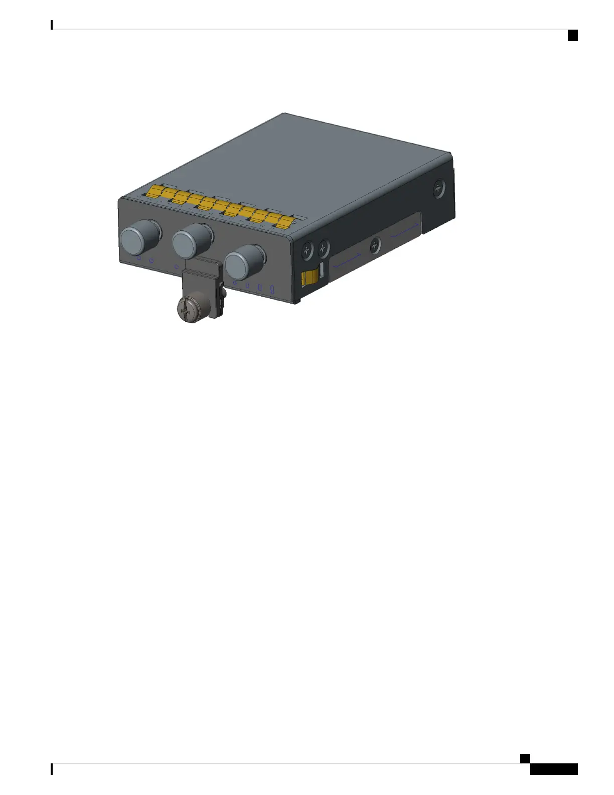
Figure 24: USB Cover Finished Installation
Step 8 Slide the Pluggable Module into the device as shown in Figure 25: Pluggable Module Insert, on page 42. The latch
lock screw (1) aligns with the screw hole (2) on the front of the device. Push the Pluggable Module all the way into the
device until you feel it seat, and then torque the latch lock screw 8-10 inch-pound (0.9 to 1.1 newton meter).
IR1101 Industrial Integrated Services Router Hardware Installation Guide
41
Installing the Router
Pluggable Module