4-14
Catalyst 4500 E-Series Switches Installation Guide
OL-13972-02
Chapter 4 Removal and Replacement Procedures
Removing and Installing the Chassis Fan Tray Assembly
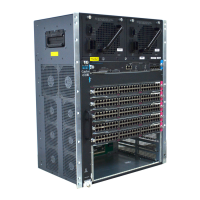
Figure 4-15 Catalyst 4506-E System Fan Tray Assembly
Step 2 Grasp the fan tray assembly handle and slide the fan tray assembly out of the chassis; gently move it side
to side if necessary to unseat it from the backplane. Remove the fan tray assembly from the chassis and
set it aside.
Installing the Fan Tray Assembly
To install the replacement fan tray assembly, follow these steps:
Step 1 Remove the replacement fan tray assembly from the shipping packaging.
Step 2 Hold the fan tray assembly with the fans facing to the right.
Step 3 Place the fan tray assembly into the fan tray assembly bay so it rests on the chassis, and then lift the fan
tray assembly up slightly, aligning the top and bottom guides.
Step 4 Slide the fan tray assembly into the chassis until the two captive installation screws make contact with
the chassis.
Step 5 Tighten the two captive installation screws to secure the fan tray assembly in the chassis.
1 Captive installation screws 2 Fan tray assembly
231372
4506
2
1
 Loading...


