3-9
Catalyst 4500 E-Series Switches Installation Guide
OL-13972-02
Chapter 3 Installing the Switch
Completing the Installation Process
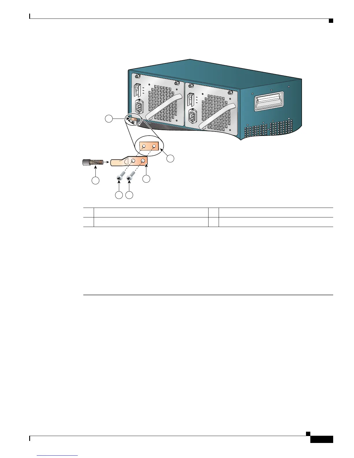
Figure 3-3 Connecting System Ground on the Switch
Step 5 Place the grounding lug against the grounding pad making sure there is good metal-to-metal contact
between the lug and the bare metal of the chassis and that the grounding lug and the attached wire will
not interfere with other switch hardware or rack equipment.
Step 6 Secure the system ground lug to the chassis with the two M4 screws.
Step 7 Prepare the other end of the grounding wire and connect it to an appropriate grounding point at your site
to ensure adequate earth ground for the switch. Consult with your local electrician to determine the
appropriate place to attach the gound wire.
Completing the Installation Process
Perform the following procedures to complete the installation process.
Attaching the Power Cords
Verify that you have the correct power supply (AC-input or DC-input and the correct wattage) for your
configuration. Connect the chassis power supplies to the site power by referring to the
“Removing and
Installing the AC-Input Power Supplies” section on page 4-2 or the “Removing and Installing the
DC-Input Power Supplies” section on page 4-8.
1 System grounding wire 3 Grounding lug
2 Screws (M4) 4 Chassis grounding pad
231374
4503
3
4
2
1
2
4
 Loading...


