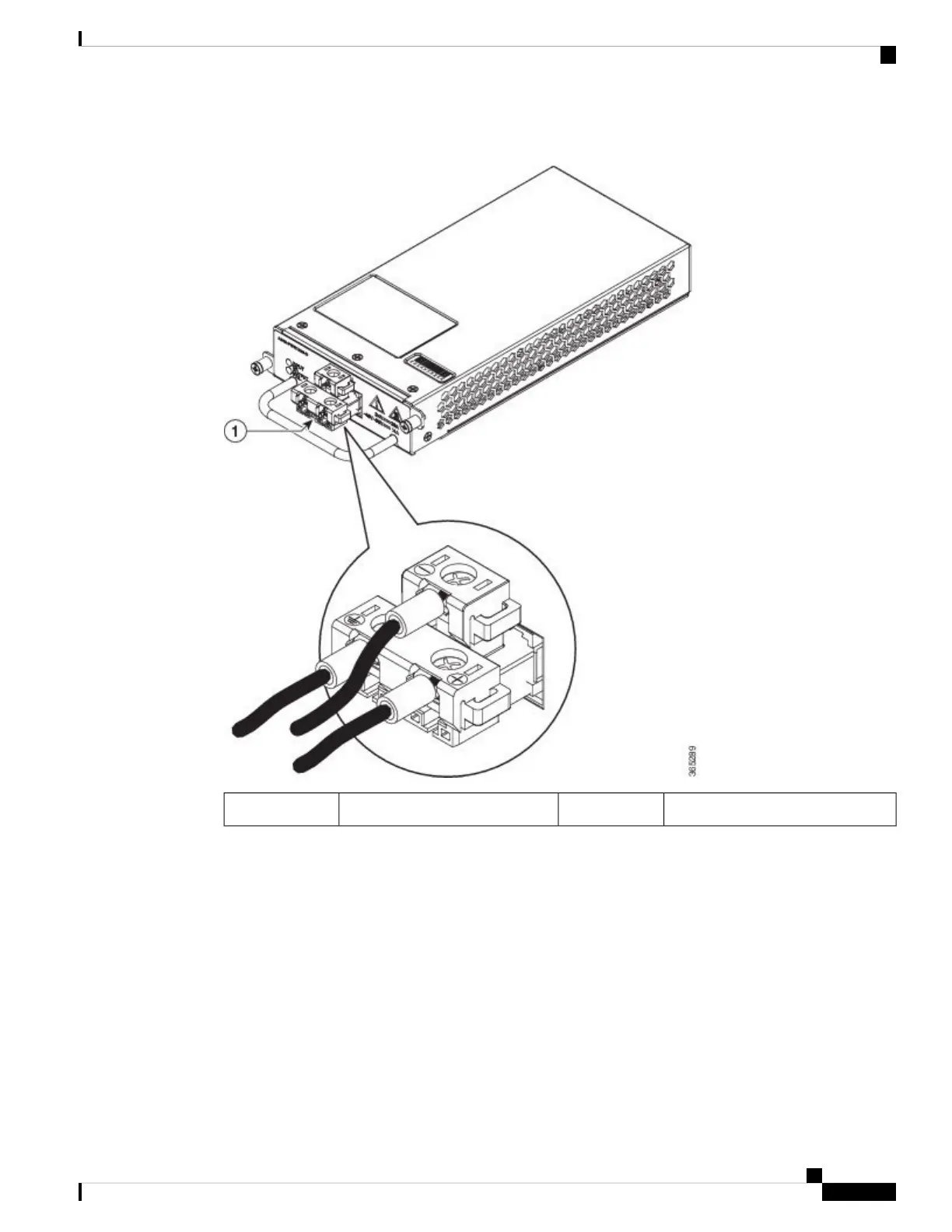
Figure 38: A900-PWR1200-D DC Power Supply
——T-shaped connector1
Step 4 Use a wire-stripping tool to strip the ends of each of the two wires coming from the DC-input power source
to 0.27 inch (6.6 mm) ± 0.02 inch (0.5 mm) and the wire for grounding. Do not strip more than 0.29 inch (7.4
mm) of insulation from the wire. Stripping more than the recommended amount of wire can leave behind
exposed wire from the terminal block after installation.
Step 5 Use the appropriate crimping tool as suggested by the manufacture.
Step 6 Prepare the cables by attaching the lugs to the cables.
Step 7 Identify the ground, positive, and negative feed positions for the terminal block connection. The recommended
wiring sequence is:
• Negative (-) lead wire (top)
• Ground lead wire (left)
• Positive (+) lead wire (right)
Cisco NCS 560-4 Router Hardware Installation Guide
71
Installing the Cisco NCS 560-4 Router
Installing the A900-PWR1200-D DC Power Supply Module