Send document comments to nexus7k-docfeedback@cisco.com
4-21
Cisco Nexus 7000 Series Hardware Installation and Reference Guide
OL-23069-06
Chapter 4 Installing a Cisco Nexus 7018 Chassis
Installing the Front Door and Air Intake Frame
To install the front door and air intake frame to the Cisco Nexus 7018 cable management system, follow
these steps:
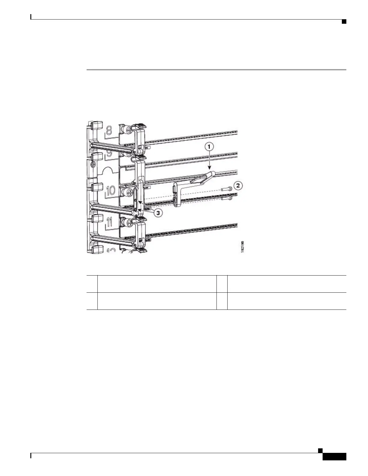
Step 1 Position the left door stopper (700-27454-01) on the middle of the left cable management frame and
fasten it with two M3x10 pan-head screws as shown in Figure 4-13. Tighten these two screws to 5 to 7
in-lb (0.6 to 0.8 N·m).
Figure 4-13 Attaching the Left Door Stopper
Step 2
Position the right door stopper (700-27592-01) on the middle of the right side of the cable management
frame and fasten it with two M3x10 pan-head screws as shown in Figure 4-14. Tighten these two screws
to 5 to 7 in-lb (0.6 to 0.8 N·m).
1 Left door stopper identified with an L on the
bottom of the base.
3 Screw holes on the cable management frame.
2 Two M3x10 screws that fasten the stopper to
the cable management frame.

 Loading...


