Step 2 Strip 1/2-inch of insulation off the DC wires you will use.
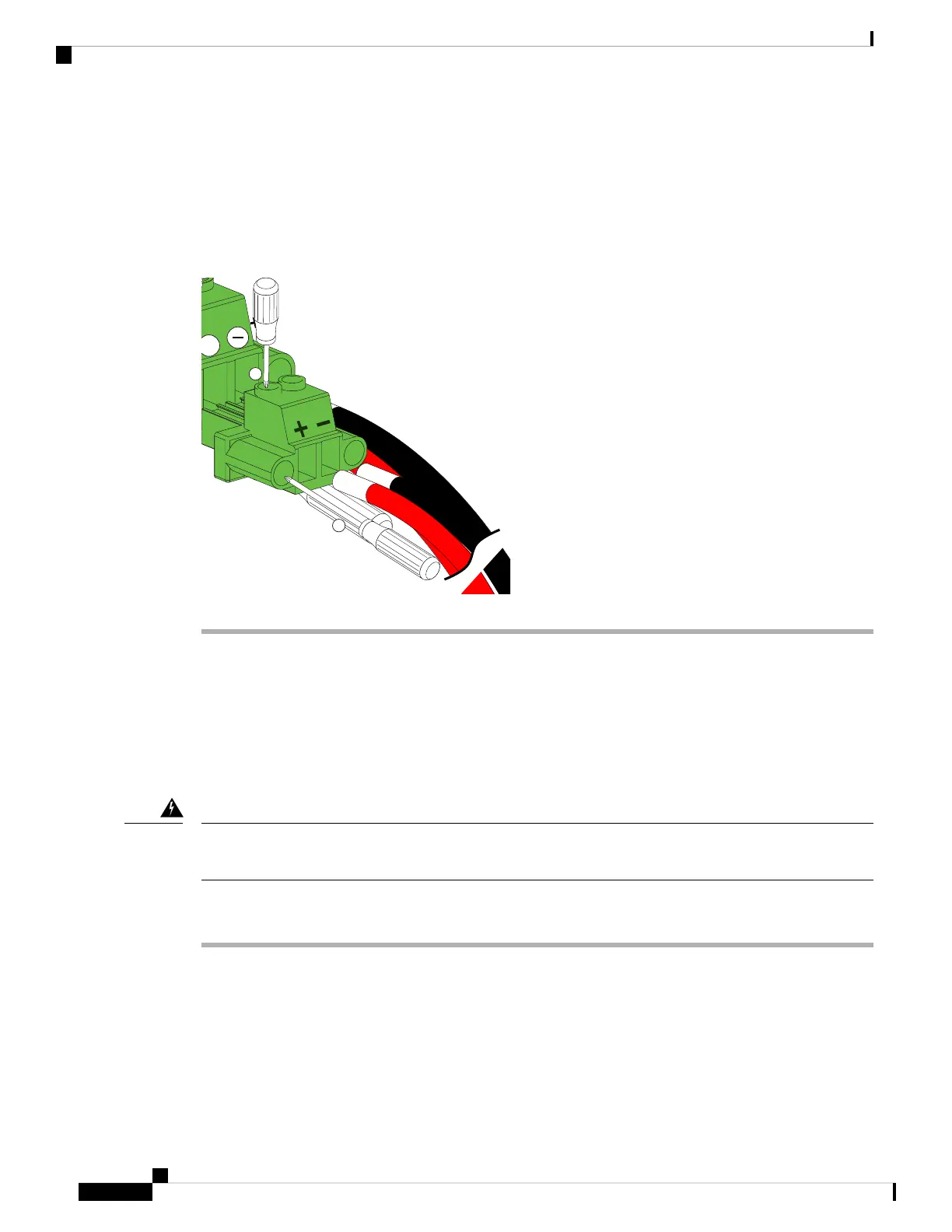
Step 3 Insert the black (DC negative) wire into the right aperture on the connector and tighten down the connection
set screw. Finger tight or about 3 ft./lbs should be sufficient.
Step 4 Insert the red (DC positive) wire into the left aperture on the connector and tighten down the connection set
screw. Do not tighten over 0.7 Nm.
Figure 31: Wiring the DC Power Connector
Fan Modules
The fan module is designed to be removed and replaced while the system is operating without presenting an
electrical or thermal hazard or damage to the system, provided that the replacement is performed promptly.
Replacing a Fan Module
When removing the fan tray, keep your hands and fingers away from the spinning fan blades. Let the fan
blades completely stop before you remove the fan tray. Statement 258
Warning
Procedure
Step 1 Ensure that the system (earth) ground connection has been made.
Step 2 Loosen the captive screws on the fan module by turning them counterclockwise, using a flat-blade or number 2
Phillips head screwdriver if required.
Step 3 Grasp the handle of fan module and pull it outward.
Step 4 Pull the fan module clear of the chassis and set it down on antistatic foam or place it in an antistatic bag.
Step 5 Hold the replacement fan module with the LED at the bottom.
Cisco UCS 6200 Series Fabric Interconnect Hardware Installation Guide
OL-24475-0346
Installing the Cisco UCS 6200 Series Fabric Interconnect
Fan Modules