EasyManuals Logo

Cisco UCS B200 M5 User Manual

Cisco UCS B200 M5
74 pages
To Next Page IconTo Next Page
To Previous Page IconTo Previous Page
Page #58 background imageLoading...
Page #58 background image
Procedure
Step 1
Use the T-shaped wrench that comes with the GPU to remove the existing standoff at the back end of the
motherboard.
Step 2
Install the custom standoff in the same location at the back end of the motherboard.
Step 3
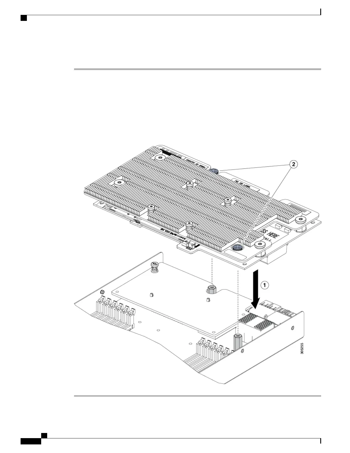
Position the CPU over the connector on the motherboard and align all the captive screws to the standoff posts
(callout 1).
Step 4
Tighten the captive screws (callout 2).
Figure 24: Installing the NVIDIA P6 GPU in the Rear Mezzanine Slot
Cisco UCS B200 M5 Blade Server Installation and Service Note
48
Servicing a Blade Server
Installing an NVIDIA GPU Card in the Rear of the Server

Table of Contents

Questions and Answers:

Question and Answer IconNeed help?

Do you have a question about the Cisco UCS B200 M5 and is the answer not in the manual?

Cisco UCS B200 M5 Specifications

General IconGeneral
Form FactorBlade
ProcessorIntel Xeon Scalable Processors
ManagementCisco UCS Manager
Processor Sockets2
Product TypeBlade Server
MemoryUp to 3 TB DDR4
Memory Slots24 DIMM slots
StorageUp to 2 x SAS/SATA drives
Expansion SlotsMezzanine card
RAID SupportRAID 0, 1
Network10 Gigabit Ethernet, 25 Gigabit Ethernet
Power SupplyPart of UCS Blade Server Chassis

Related product manuals