Model CFC ClearFire Commercial Boilers
11 Rev. 05-2012
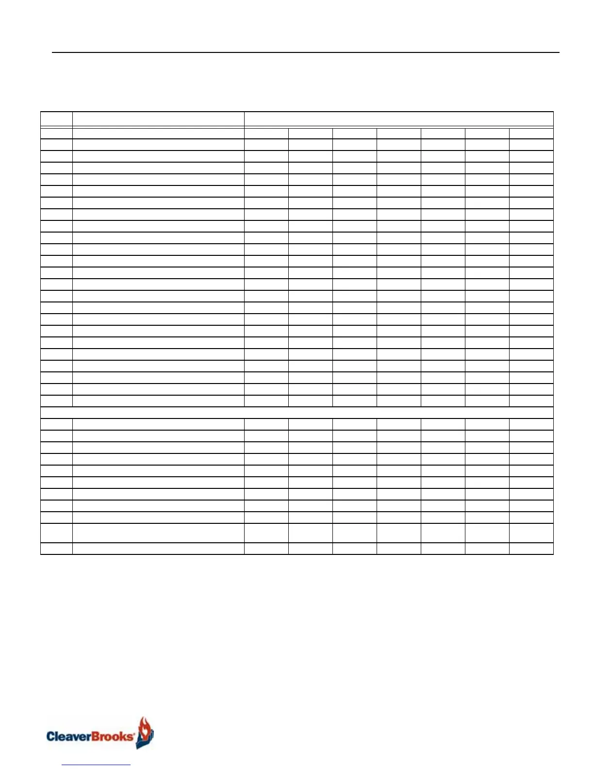
Table B5-2. Metric Dimensions Model CFC Boiler
Boiler Size
ITEM DIMENSIONS (mm) 500 750 1000 1500 1800 2500 3300
A Overall Height 1824 1824 1923 2073 2073 2088 2159
B Overall Width 820 820 930 1110 1110 1290 1557
C Overall Depth 1240 1240 1590 1666 1666 1844 2192
D Width Less Casing 681 681 790 970 970 1151 1410
E Gas Connection to Top of Casing 206 206 241 318 259 239 254
F Gas Connection to Floor 1618 1618 1681 1755 1814 1849 1905
G Side of Casing to Gas Connection 58 58 109 86 132 119 130
H Boiler Centerline to Air Inlet Centerline 102 102 102 124 180 180 180
I Floor to Bottom of Base 262 262 262 262 262 262 262
J Floor to Top of Stack Connection 472 472 460 485 485 531 544
K Centerline to Centerline of Stack Stub 391 391 429 533 533 714 909
L Rear of Boiler to Centerline of Stack Stub 137 137 191 206 206 218 254
M Front of Boiler to Rear of Casing 986 986 1255 1257 1257 1435 1702
N Control Panel Projection 104 104 104 104 104 104 109
O Casing Height 1427 1427 1524 1661 1661 1661 1702
P Air Vent Line Projection from Rear of Casing 198 198 185 206 206 221 119
Q Floor to Centerline of Lower Return 495 495 498 526 541 569 612
R Floor to Centerline of Upper Return 716 729 775 516 820 859 902
S Floor to Centerline of Supply Connection 1379 1379 1427 1450 1427 1427 1501
T Floor to Centerline of Air Vent 1521 1521 1582 1603 1603 1615 1687
AA Boiler Adjustment Foot Height 64 64 64 64 64 64 64
Height Above Boiler for Burner Service 356 356 356 356 356 356 457
CONNECTIONS (inches)
U Water Supply/Return, 150# RF Flg 2-1/2" 2-1/2" 2-1/2" 3" 4" 5" 5"
V Boiler Air Vent, NPT 1-1/2" 1-1/2" 1-1/2" 1-1/2" 1-1/2" 1-1/2" 1-1/2"
W Electrical Conduit, left or right 1.6" 1.6" 1.6" 1.6" 1.6" 1.6" 1.6"
X Boiler Drain, NPT 1-1/2" 1-1/2" 1-1/2" 1-1/2" 1-1/2" 1-1/2" 1-1/2"
Y Flue Gas Nominal OD, Left or Right option 6" 6" 8" 10" 12" 12" 12"
Z Combustion Air Option 4" 4" OR 6" 4" OR 6" 6" 6" 6" OR 8" 8"
BB Gas Connection, NPT 1 "1 "1 "1-1/2 "1-1/2 "1-1/2 "2"
CC Condensate Drain, FPT 3/4 "3/4 "3/4 "3/4 "3/4 "3/4 "1"
Relief Valve outlet @ 125 # Setting 1 "1 "1 "1 "1 "1 "1"
Voltage Fan Motor 115/1/60 115/1/60 115/1/60 115/1/60 115/1/60 115/1/60 208-240/
3/60
Voltage Control Circuit 115/1/60 115/1/60 115/1/60 115/1/60 115/1/60 115/1/60 115/1/60