To assemble the EXPLORER 3075GX
98-144390-A Chapter 3: Assembly & start up 3-5
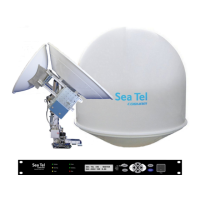
10.Latch the two bottom panels using the two smaller latches along the edge of each panel
to carefully secure the reflector panels into place.
11.Insert and latch the two upper panels.
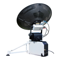
12.Connect the three cables as shown in the following figure:
BUC power cable (Gray) to MIL connector
Transmit (Red, Tx) cable IFL RG-6 to the BUC Transmit port
Receive (Blue, Rx) cable IFL RG-6 to the LNB Receive port.
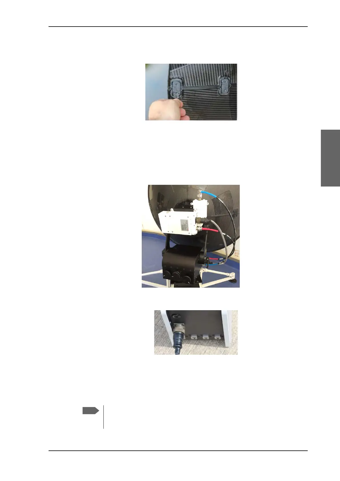
13.Connect the AC Power Adaptor to the electronics enclosure.
14.Use the four RJ-45 ports for making IP-data connections. There are two separate
functions accessible:
LAN1 (leftmost): Access to the web interface (setup and troubleshooting)
LAN2 to LAN4: Internet use etc.
Figure 3-7: Latches to interconnect the four panels
Figure 3-8: Transmit, Receive and BUC cables
Figure 3-9: AC power connection
The web interface can only be accessed via LAN1 (leftmost). The Wi-fi
connection must be configured, see To configure the LAN network on page 4-6
and WLAN settings on page 4-8.