InteliMains 210 Global Guide
35
Shielded cable
1
has to be used, shielding has to be connected to the terminal T01 (Grounding).
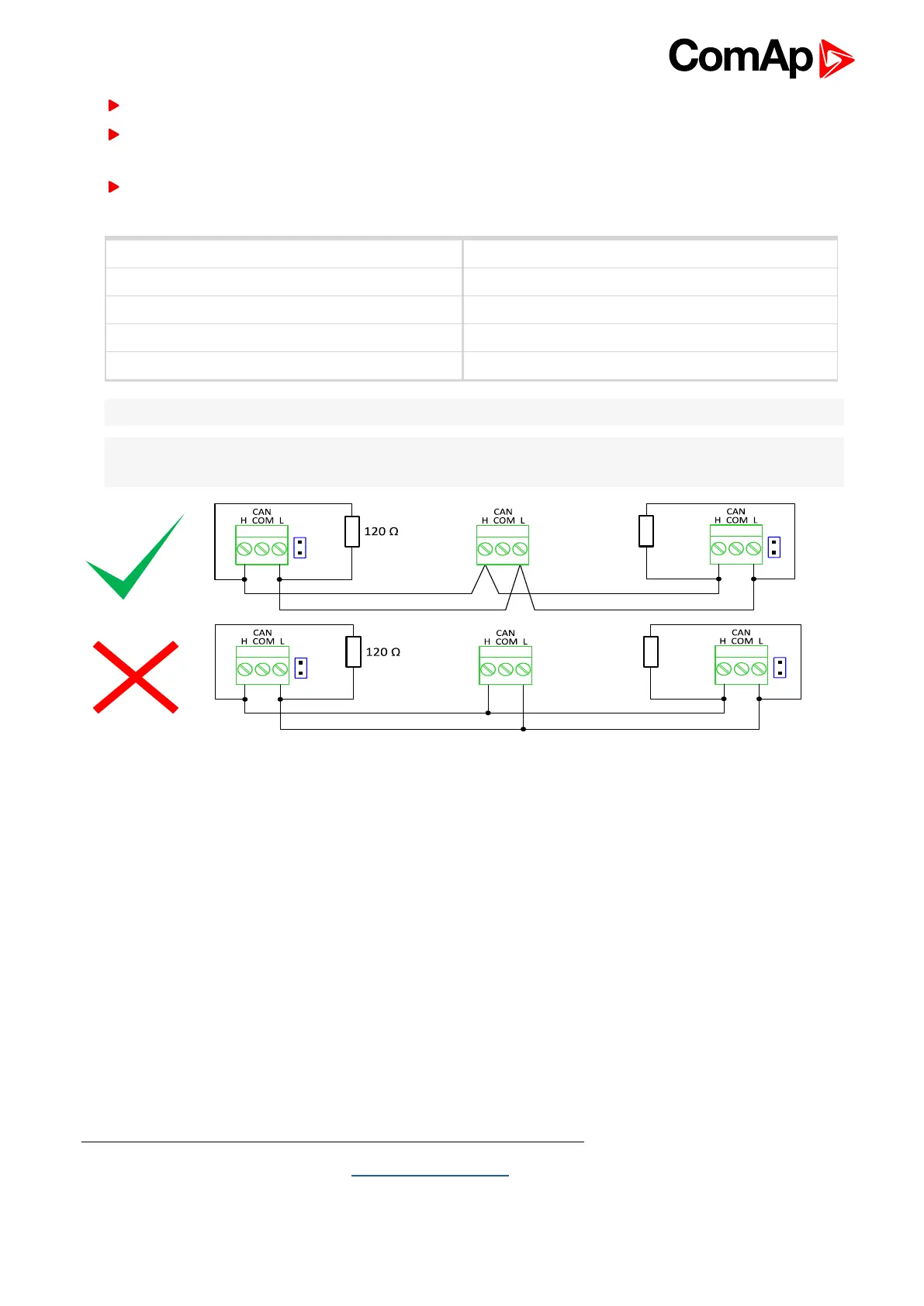
External units can be connected on the CAN bus line in any order, but keeping line arrangement (no tails, no
star) is necessary.
The CAN bus has to be terminated by 120 Ohm resistors at both ends use a cable with following
parameters:
Cable type Shielded twisted pair
Impedance 120 Ω
Propagation velocity ≥ 75% (delay ≤ 4,4 ns/m)
Wire crosscut ≥ 0,25 mm
2
Attenuation (@1MHz) ≤ 2 dB/100 m
Note: Communication circuits shall be connected to communication circuits of Listed equipment.
Note: A termination resistor at the CAN (120 Ω) is already implemented on the PCB. For connecting, close the
jumper near the appropriate CAN terminal.
Image 4.10 CAN bus topology
1
Recommended data cables: BELDEN (http://www.belden.com) - for shorter distances: 3105A Paired - EIA
Industrial RS-485 PLTC/CM (1x2 conductors); for longer distances: 3106A Paired - EIA Industrial RS-485
PLTC/CM (1x2+1 conductors)