76 Ruckus ICX 7450 Switch Hardware Installation Guide
Part Number: 53-1003899-09
Ruckus ICX 7450 Specifications
Ethernet
Ethernet
These are standard modules for shipping bundles. For Ruckus ICX 7450 non-bundled switches, expansion modules need to be ordered
separately.
LEDs
Other
System component Description Maximum ports supported
40 GbE QSFP+ ports 1 40 GbE QSFP+ stacking or uplink port 3 (slot 2-4) for ICX 7450-24/24P
2 (slot 3-4) for ICX 7450-48/48P/48F/32ZP
10 GbE SFP+ ports 4 10 GbE SFP+ uplink ports 12 (slot 2-4)
10 GbE copper ports 4 10 GbE RJ-45 uplink ports 12 (slot 2-4)
1 GbE SFP ports (optional
modules)
4 1 GbE SFP uplink ports 12 (slot 2-4)
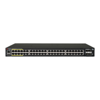
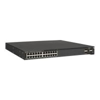
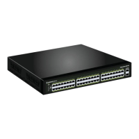
1 GbE RJ-45 front-panel ports 24 1 GbE RJ-45 ports for ICX 7450-24/24P/32ZP
48 1 GbE RJ-45 ports for ICX 7450-48/48P
24/48 (slot 1)
2.5 GbE RJ-45 front-panel ports 8 2.5 GbE RJ-45 ports for ICX 7450-32ZP 8 (slot 1)
1 GbE SFP front-panel ports 48 1 GbE SFP for ICX 7450-48F 48 (slot 1)
Ethernet management port 1 RJ-45 port with 10/100/1000 Mbps auto-negotiating
capability
N/A
System component Description
Switch status and
management
Six LED types indicate switch status:
PSU (power supply unit)
DIAG (diagnostics)
MS (stacking configuration)
Stack ID (1-12)
MOD (expansion module or service module)
PWR (expansion module or service module power)
Ports LEDs indicate port status (speed and link/activity) and PoE status (on and off)
System component Description
Serial cable 1 (Mini-USB to RJ-45)
RJ-45 to DB9 adapter 1
AC power cord, power clip For ICX 7450-24, 24P, 48, 48P, and 48F units
 Loading...