EasyManua.ls Logo

Compal NBLB2 - Removing the Battery Pack

Compal NBLB2
152 pages
Print Icon
To Next Page IconTo Next Page
To Previous Page IconTo Previous Page
Loading...
NBLB2 Service Manual
75
CAUTION
Danger of explosion if battery is incorrectly replaced.
Replace only with the same or equivalent type recommended by the
manufacturer.
Dispose of used batteries according to the manufacturer‟s instructions.
4. Power interface
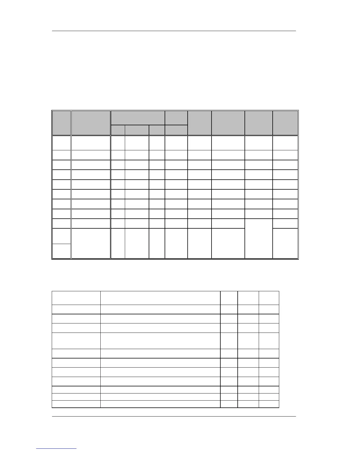
4.1 Power requirement
Item
Description
Load
Voltag
e
Ripple /
Noise
Tolerance
Control
signal
Remark
Min.
Max.
Peak
Normal
1
+CPU_CORE
0
48A
By VID
control
CPU
spec.
CPU spec
VR_ON
2
+0.75V
0
0.6A
0.75
5%
SYSON#
3
+1.1VS_VTTP
0
12.6A
1.1V
5%
SUSP#
4
+1.0VS
0
0.7A
1.0V
5%
SUSP#
5
+1.5V
0
19.92A
1.5V
5%
SYSON
6
+1.05VS
0
3.2A
1.8V
5%
SUSP#
7
+1.8V
0
3.5A
1.8V
5%
SUSP#
8
+3VS
0
2.92A
3.3V
5%:
SUSP#
9
+3VALW
0
5.8A
3.3V
5%
*1
10
+5VALW
0
5.8A
5V
5%
11.
+5VS
0
3.187A
5V
5%
SUSP#
*1: Always on when AC exist no AC exist control by EC_ON
4.2 Power/EE Interface definition:
Voltage Rails
Power Plane
Description
S1
S3
S5
VIN
Adapter Power supply (19V)
N/A
N/A
N/A
B+
AC or battery Power rail for power circuit.
N/A
N/A
N/A
+CPU_CORE
Core voltage for CPU
ON
OFF
OFF
+0.75VS
0.75V switched power rail for DDR
terminator
ON
OFF
OFF
+1.05VS
1.05V switched power rail
ON
OFF
OFF
+1.1VS
1.1VS switched power rail
ON
OFF
OFF
+1.5VS
1.5VS switched power rail
ON
OFF
OFF
+1.8V
1.8V switched power rail
ON
ON
OFF
+3VALW
3.3V always on power rail
ON
ON
ON*
+3VS
3.3V switched power rail
ON
OFF
OFF
+5VALW
5V always on power rail
ON
ON
ON*

Table of Contents

Related product manuals