2-12 Compaq 1000 Series UPS Operation and Reference Guide
5 4 3 2 1
10 9 8 7 6
15 14 13 12 11
16171819
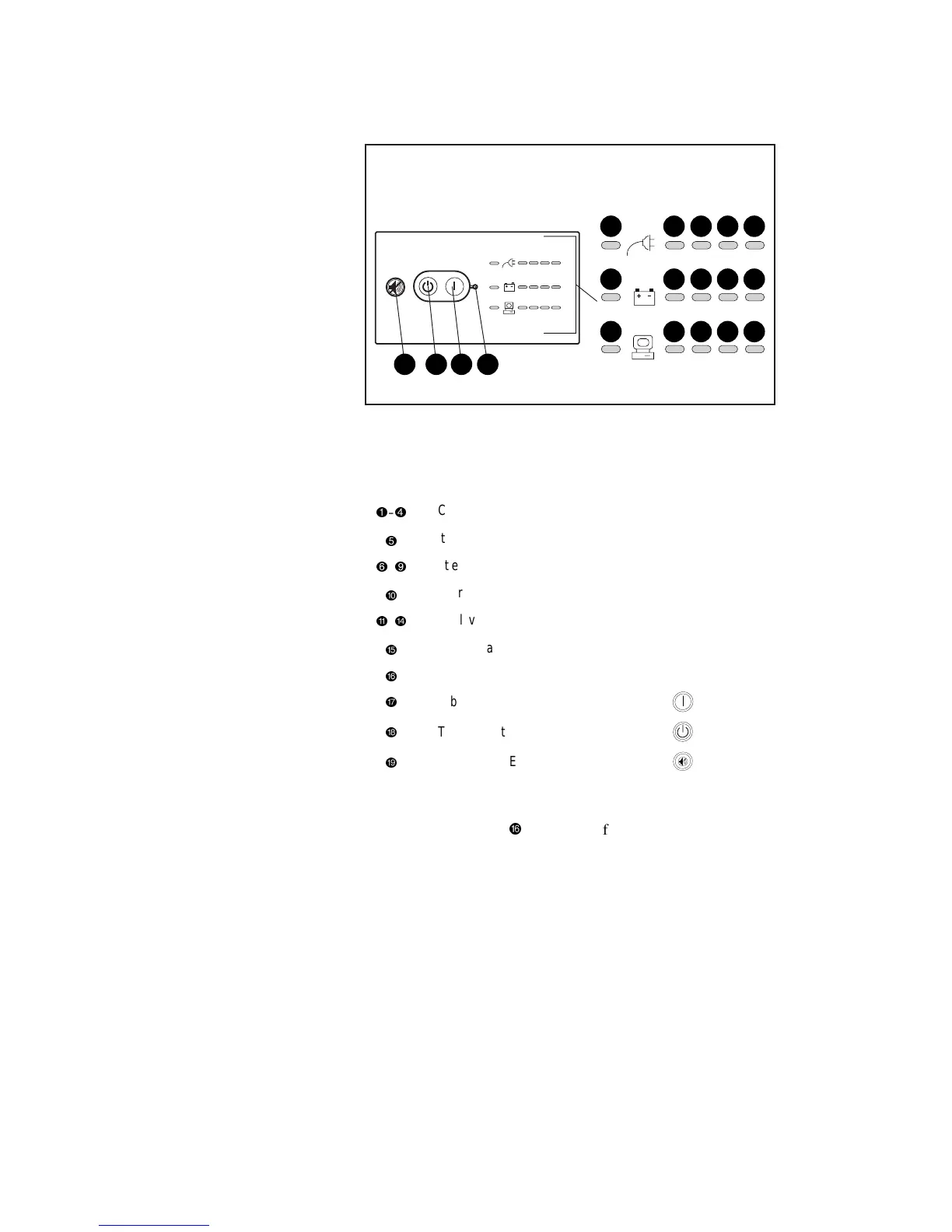
Figure 2-7. The front panel LED display (rack-mountable model)
The Front Panel LED Display – All Models
Symbol
1
–
4
AC Input level Power cord
5
Site Wiring Fault indicator
6
–
9
Battery Charge level Battery
:
Battery Service indicator
q
–
r
Load level Load devices
t
Communications
y
ON LED
A
ON button
i
STANDBY button
C
TEST/ALARM RESET button
Check the front panel LED display:
■ LED 16 (ON LED,
@
) should be off, indicating that no power is
available at the UPS output receptacles.
■ Either AC Input LED 2 or 3 should be green, indicating the utility
voltage is suitable.
■ LEDs 6, 7, 8, and 9 indicate the battery charge level.
 Loading...