Technical Reference Guide
Compaq iPAQ Series of Desktop Personal Computers
Second Edition - February 2001
7-5
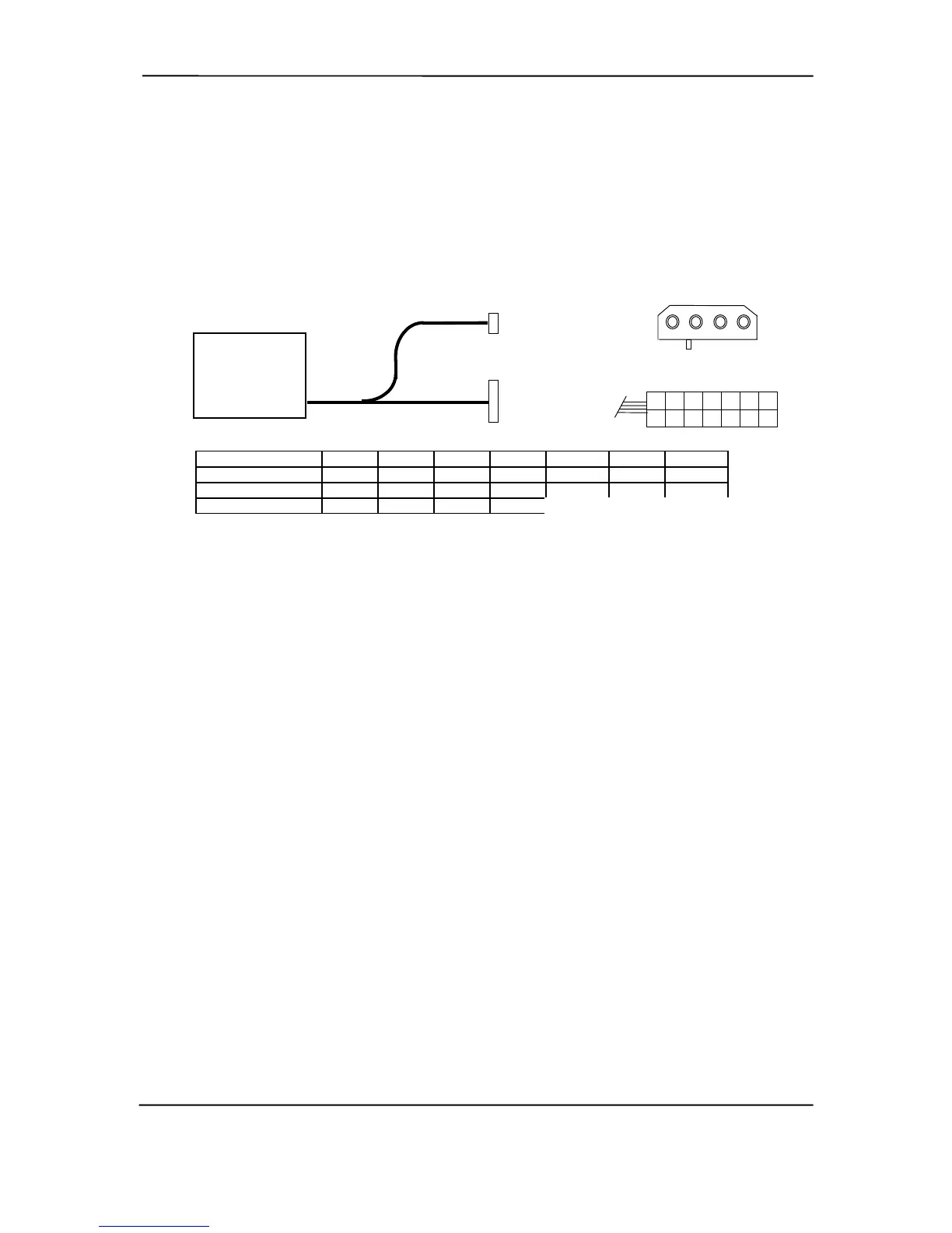
7.3.1.2 iPAQ 2.0 POWER DISTRIBUTION
The iPAQ 2.0 power supply assembly includes a multi-connector cable assembly that routes +3.3
VDC, +5 VDC, -5 VDC, +12 VC, and -12 VDC to the system board as well as to the individual
drive assemblies. Figure 7-3 shows the power supply cabling.
Conn. # Pin 1 Pin 2 Pin 3 Pin 4 Pin 5 Pin 6 Pin 7
P1 +3.3 +5 RTN +5 RTN +5 RTN
P1 [1] +3.3 -12 FO PS On +5 Aux RTN +12
P3 +12 GND GND +5
NOTES:
[1] This row represents pins 8-14 of connector P1.
All + and - values are VDC
.
RTN = Return (signal ground)
GND = Power ground
PS On = Power supply on
FO = Fan off
Figure 7–3. iPAQ 2.0 Power Cable Diagram
Power Supply
Assembly
(P/N 216922
or 218584)
P1
P3
1 2 3 4
P3
P1
1 2 5 4 3 7 6
10 11 12 13 14 8 9