Technical Reference Guide
Compaq iPAQ Series of Desktop Personal Computers
Second Edition - February 2001
2-15
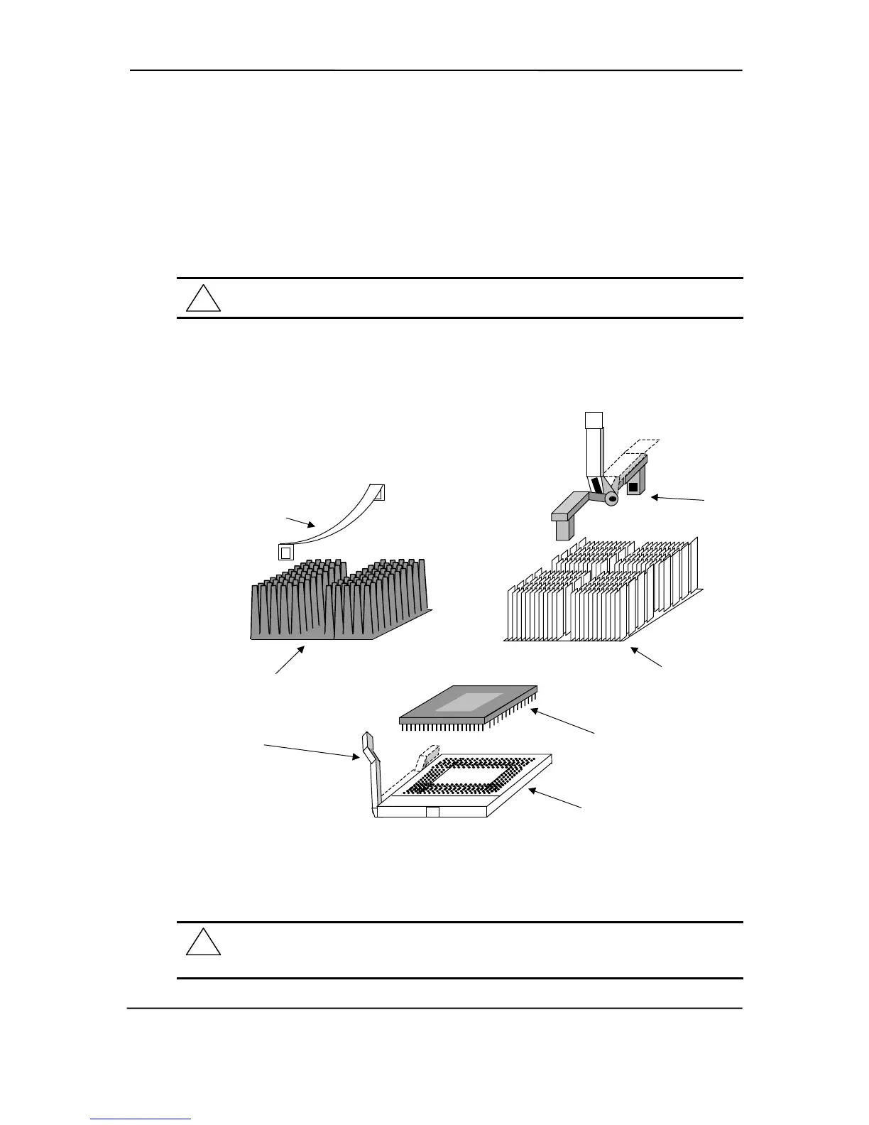
2.4.3.3 Processor Upgrading
All models of the Compaq iPAQ use the PGA370 zero-insertion force (ZIF) socket for processor
mounting as shown in Figure 2-10. The processor assembly includes a heat sink attached by a
retaining clip or bar. Replacing the processor requires removal of the heat sink followed by
removal of the processor. On iPAQ 2.0 systems, the heat sink is held in place by a retaining bar
with it’s own locking handle.
CAUTION: Refer to section 3.2.2 (Chapter 3) for a description of the removal and
replacement of the processor assembly.
Factory configurations use processors fitted with passive heat sinks.
Figure 2–10. Processor Assembly and Mounting
WARNING: The iPAQ 1.0/1.2 system board is designed handle a maximum processor
current load of 18 amps. Installing a replacement processor that draws more than 18 amps
of current may damage the processor and/or the system board.
!
!
Heat Sink
(iPAQ 1.x)
PPGA370
Socket
Heat Sink
Retaining Clip
Processor
Lock/Unlock
Handle
Processor in
Flip-Chip Package
Heat Sink
(iPAQ 2.0)
Heat Sink
Retaining Bar
(iPAQ 2.0)