Technical Reference Guide
Compaq iPAQ Series of Desktop Personal Computers
Second Edition - February 2001
4-9
4.3.1.2 Non-Maskable Interrupts
Non-maskable interrupts cannot be masked (inhibited) within the microprocessor itself but may be
maskable by software using logic external to the microprocessor. There are two non-maskable
interrupt signals: the NMI- and the SMI-. These signals have service priority over all maskable
interrupts, with the SMI- having top priority over all interrupts including the NMI-.
NMI- Generation
The Non-Maskable Interrupt (NMI-) signal can be generated by either a parity error detected on a
PCI bus (activating SERR- or PERR-) or by an internal processor error (activating IERRA or
IERRB).
The SERR- and PERR- signals are routed through the ICH component, which in turn activates the
NMI to the microprocessor. The NMI Status Register at I/O port 061h contains NMI source and
status data as follows:
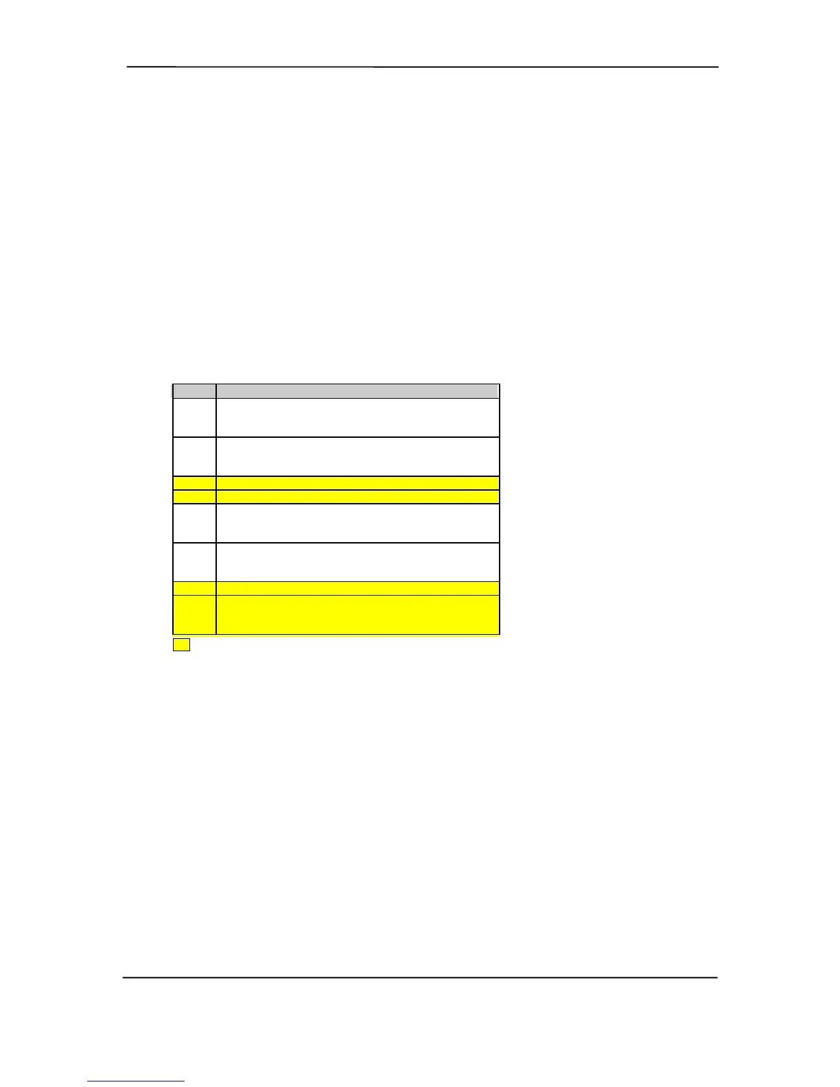
NMI Status Register 61h
Bit Function
7 NMI Status:
0 = No NMI from system board parity error.
1 = NMI requested, read only
6IOCHK- NMI:
0 = No NMI from IOCHK-
1 = IOCHK- is active (low), NMI requested, read only
5 Interval Timer 1, Counter 2 (Speaker) Status
4 Refresh Indicator (toggles with every refresh)
3 IOCHK- NMI Enable/Disable:
0 = NMI from IOCHK- enabled
1 = NMI from IOCHK- disabled and cleared (R/W)
2 System Board Parity Error (PERR/SERR) NMI Enable:
0 = Parity error NMI enabled
1 = Parity error NMI disabled and cleared (R/W)
1 Speaker Data (R/W)
0 Inteval Timer 1, Counter 2 Gate Signal (R/W)
0 = Counter 2 disabled
1 = Counter 2 enabled
After the active NMI has been processed, status bits <7> or <6> are cleared by pulsing bits <2> or
<3> respectively. The NMI Enable Register (070h, <7>) is used to enable/disable the NMI signal.
Writing 80h to this register masks generation of the NMI-. Note that the lower six bits of register at
I/O port 70h affect RTC operation and should be considered when changing NMI- generation
status.
SMI- Generation
The SMI- (System Management Interrupt) is typically used for power management functions.
When power management is enabled, inactivity timers are monitored. When a timer times out,
SMI- is asserted and invokes the microprocessor’s SMI handler. The SMI- handler works with the
APM BIOS to service the SMI- according to the cause of the timeout. Although the SMI- is
primarily used for power managment the interrupt is also employed for the QuickLock/QuickBlank
functions as well.
Functions not related to NMI activity.