13
13) Ensure that faces of the opposing 90
o
adjustment angles are square and parallel to each
other.
14) Set the pit channel in place with the centerline between rails and center back to front with
the center of rails. Leave the pit channel loose but shim it to ensure it is level. Never just
“point shim” the pit channel. The pit channel should be shimmed over its entire length
since the pit channel supports the full weight of the lift and its rated load. Once shimmed
to be level, then fill any open spaces under the channel with a non-shrink grout to ensure
full support for the lift. The center directly under the jack upstand post must be shimmed
with steel. Do not bolt the pit channel into place at this time.
15) Remove plumb lines and loosely install rail clips onto the 90
o
adjustment angles.
16) Stand the first two rail sections in the pit channel. CAUTION: Install one rail “male side
up
” and the other “female side up”. Center the rails on the adjustment angles and loosely
install the rail clips to hold the rail in place. Use two rail clips per adjustment angle. Do not
tighten at this time. If required, lift the extra rail lengths into position making sure to match
the male to the female ends. Prior to this, clean all tongue and groove joints before
mating. Loosely attach the connecting splice plates.
NOTE
Check the shop drawing because if a short rail section is supplied, it may need to be installed
at the bottom or top.
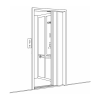
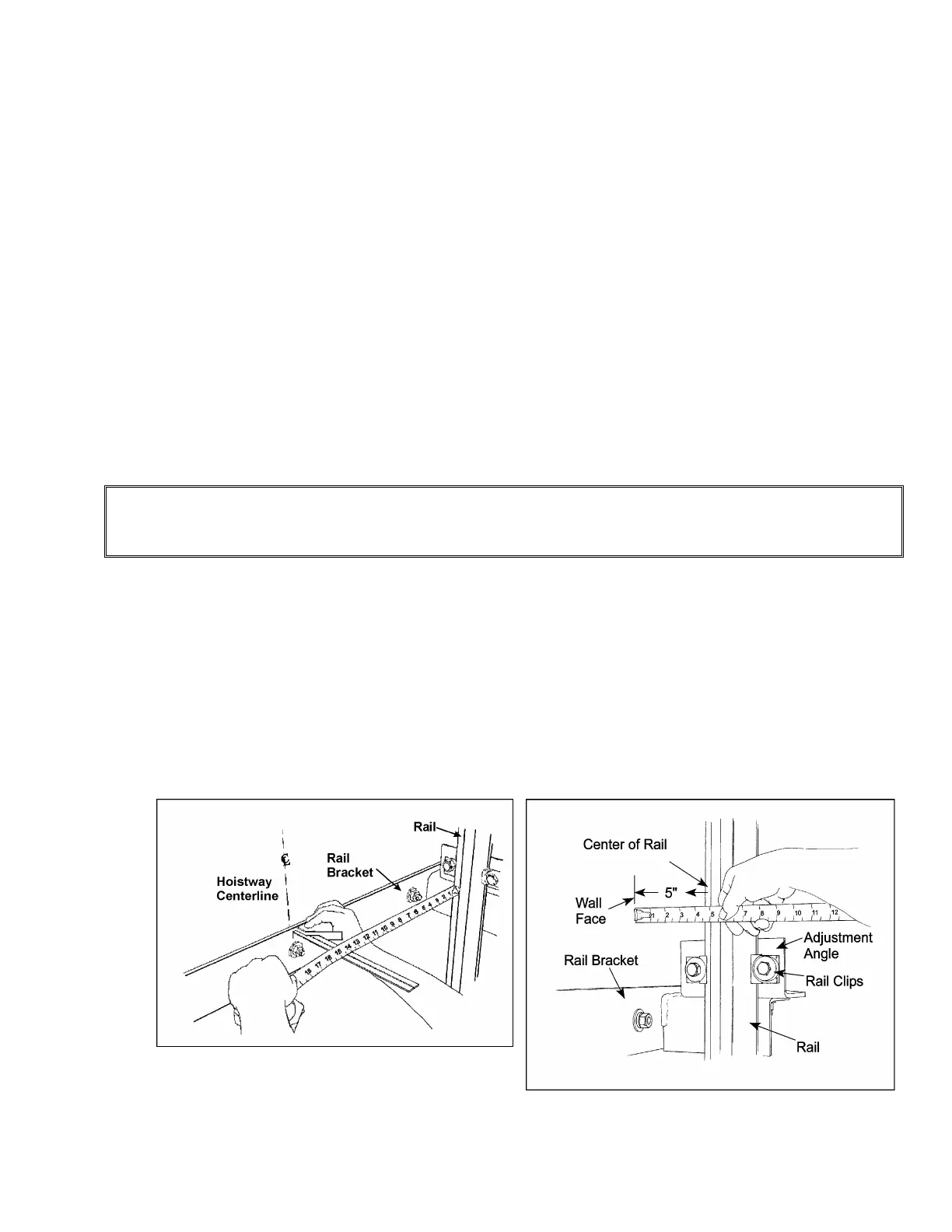
17) Rails must be plumb and square and maintain the proper D.B.G. over the entire rail
length. Check D.B.G. by measuring the distance between the rail faces and measuring
the distance from wall centerline to rail face. (See Figure # 5). To check for plumb, hang a
plumb line from a piece of flat steel clamped onto the top front face of each rail. A
plumbers clamp or “C” clamp works well here). (See Figure # 7). To keep the plumb “bob”
from swinging, suspend it in a one quart/litre can of oil. Beginning at the top ensure the
right rail sections are the same distance from the plumb line all the way down and that the
front face of the rail “line up” with the plumb line +/- 1/32". (See Figure # 8). Repeat on left
side. Check and recheck and, if required, adjust the D.B.G.
Figure # 5 Checking the D.B.G.
Figure # 6 Checking Rail Distance from Wall