67
Halfway Box Connections
Refer to Appendix A, “Electrical Schematics”, or Figure # 26 (Halfway Junction Box Board).
1) Plug in all the Traveling Cables to their appropriate terminals.
2) Connect nine (9) wires, labelled “to pump”, from the pump to the Halfway Junction Box
screw terminals. NOTE: A tenth ground wire (# 14 gauge green) must be connected
between the pump ground and the G screw terminal in the Junction Box. The green # 14
gauge wire in Traveling Cable A should also be connected to this G screw terminal. The
# 14 gauge black and white wires should be connected to the H and N screw terminals.
3) If equipped, the red and white wires should be connected to the telephone screw
terminals.
4) Connect the wires from the pit switch (normally closed) to the labelled screw terminals.
5) Connect the ten (10) wires from each hall station to the ten (10) screw terminals for each
landing in the junction box. Refer to Appendix A, “Electrical Schematics”, (supplied with
each installation) to identify which wires out of ten must be used. Wires 9 and 10 have
different functions for different locks.
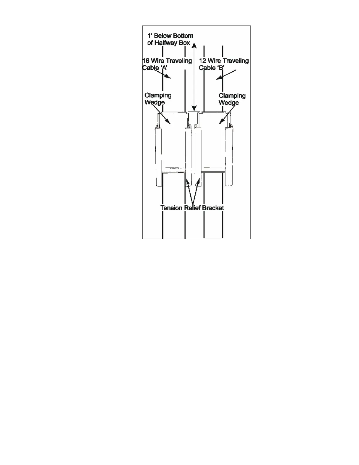
Figure # 47 Tension Relief Brackets