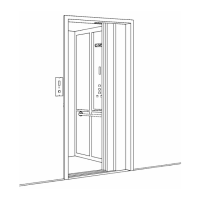
85
ELECTRICAL CONTACTS ADJUSTMENT
Observe the two electrical contacts on the carrier mounted on top of the latch bolt. When the
latch bolt is fully forward into the keeper, there should be at least 1/16" of spring compression
on each side of the contact. This indicates sufficient contact pressure to permit consistent
electrical operation. If the spring compression is less than the amount indicated, it may be
necessary to shim the keeper forward toward the lock assembly. The keeper mounting plate
may be shimmed slightly to move it closer towards the lock body in the frame. Excess
shimming may cause the plate to strike the frame when the door closes.
NOTE
The PRO-LOCK has been certified by CSA International as a true interlock. The PRO-LOCK
has also been tested and certified to the A.S.M.E. A17.1 and the CSA B44 Standards for
elevator interlocks.
INSTALLING POWER SPRINGS ON THE PRO-DOOR OPERATOR
1. If the operator is installed in the door frame header:
a) Remove the cover plate on the shaft side (hoistway) of the door header, disconnect
all the power to the lift and disconnect all wires.
b) Remove the door arm using the following procedure:
i) Open the door about half way.
ii) Remove the 1/4" screw from the arm, where it is fastened to the underside of
the frame header.
iii) The arm should easily ‘fall away’ from the fastening when the screw is
removed. If not, pry down gently with a flat blade screwdriver.
iv) Once the arm is clear of the operator attachment, it can be removed from the
door track if necessary by rolling the arm down the length of the track towards
the leading edge of the door. There is a slot at the end of the track where the
collar can exit and the arm can be removed.
c) Remove the two (2) #10 screws from the underside of the frame header on the
corridor side. These hold the operator in place.
d) The operator can now be removed.
i) If the operator is on a right-hand door it can be removed by simply pulling
straight out.
ii) If the operator is mounted on a left-hand door, then the operator must be
grasped by the motor and slid or pulled to your right to position it for removal
from the frame.
THE POWER SPRING GENERATES 260 IN/LB. OF
TORQUE. DO NOT ATTEMPT TO REMOVE THE OUTER
BAND OR PUSH THE SPRING THROUGH THE BAND.