User Manual 3Fire Detection System
5100606_CFD5000 T - CM2.2_User Manual_T_EN_2023_E
9
The loop units in the CFD5000 FDS are designed to make decisions about the fault
and alarm condition locally. This adaptation has been done in order to ensure SIL
classification of the safety function.
External interfaces
The external interfaces to the CFD5000 FDS are:
•
the xFire signal to the CCP Fire, signals the fire condition, the CFD5000 FDS
supervises the integrity of the xFire signal
•
redundant communication (2 * RS-485) from/to the CCP Fire, used to
communicate between the unsafe part of the CFD5000 FDS modules and the
CCP Fire modules
•
smoke/heat sensors, safe detection of the fire condition by detectors (CS-PYH,
CS-PH Ex and CS-ASP) on the loop-line
•
detection of user activation by Manual Call points (CS-MCP) on the loop-line
•
inputs on IO Controllers (CS-IC10, CS-IC22 and CS-PYH) on the loop-line
•
outputs (dry relay contacts) on IO Controllers (CS-IC22) on the loop-line
•
fire/fault/disabled outputs signals located on the CS-Safety M module
•
Safety data, sent from CS-Com M via SDTv2 protocol
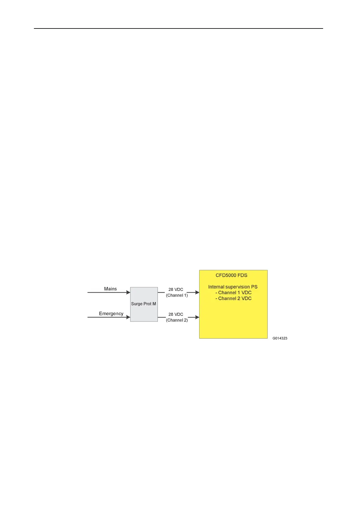
Power
The CFD5000 FDS gets power directly from the train. A passive module for
protection against EMC (surge, burst etc.) is needed.
Figure 5. Power via Surge Prot
The mains- and emergency power inputs are usually fed from the same source, the
power supplied to the power inputs is project dependent and is in this case not a
part of the safety function.
3.1.3 CFD5000 Modules
•
CS-Loop M H
•
CS-Safety M H
•
CS-Com M
For more information, see respective datasheet.