Menu 7
Parameter
structure
Keypad and
display
Parameter x.00
Parameter
description format
Advanced parameter
descriptions
Serial comms
protocol
Electronic
nameplate
Performance
102 Digitax ST Advanced User Guide
www.controltechniques.com Issue Number: 1
Table 5-6 Power stack temperature 3 (Pr 7.36) in °C
The control board temperature is also monitored and displayed in Pr 7.06. If the temperature displayed exceeds 92°C an O.Ctl trip is initiated, and this
trip can only be reset if the temperature falls below 87°C . If the temperature exceeds 85°C a "hot" alarm is displayed. If the temperature is outside
the range from -20°C to 150°C it is assumed that the monitoring thermistor has failed and an HF29 hardware fault trip is initiated.
Drive cooling fan
The drive cooling fan is controlled by the temperature from monitoring points and other actions as follows:
1. If Pr 6.45 = 1 the fan is at full speed for at least 10s.
2. If a Solutions Module indicates that it is too hot the fan is at full speed for at least 10s.
3. The fan is always on when the drive or the braking IGBT are enabled and remains on for 10s after the drive or braking IGBT is disabled.
This value can be used to trim out any offset from the user input signal
The following modes are available for the analog input 2. In modes 2 and 3 a current loop loss trip is generated if the input current falls below 3mA.
Trip temperature Trip reset temperature Alarm temperature
105 100 100
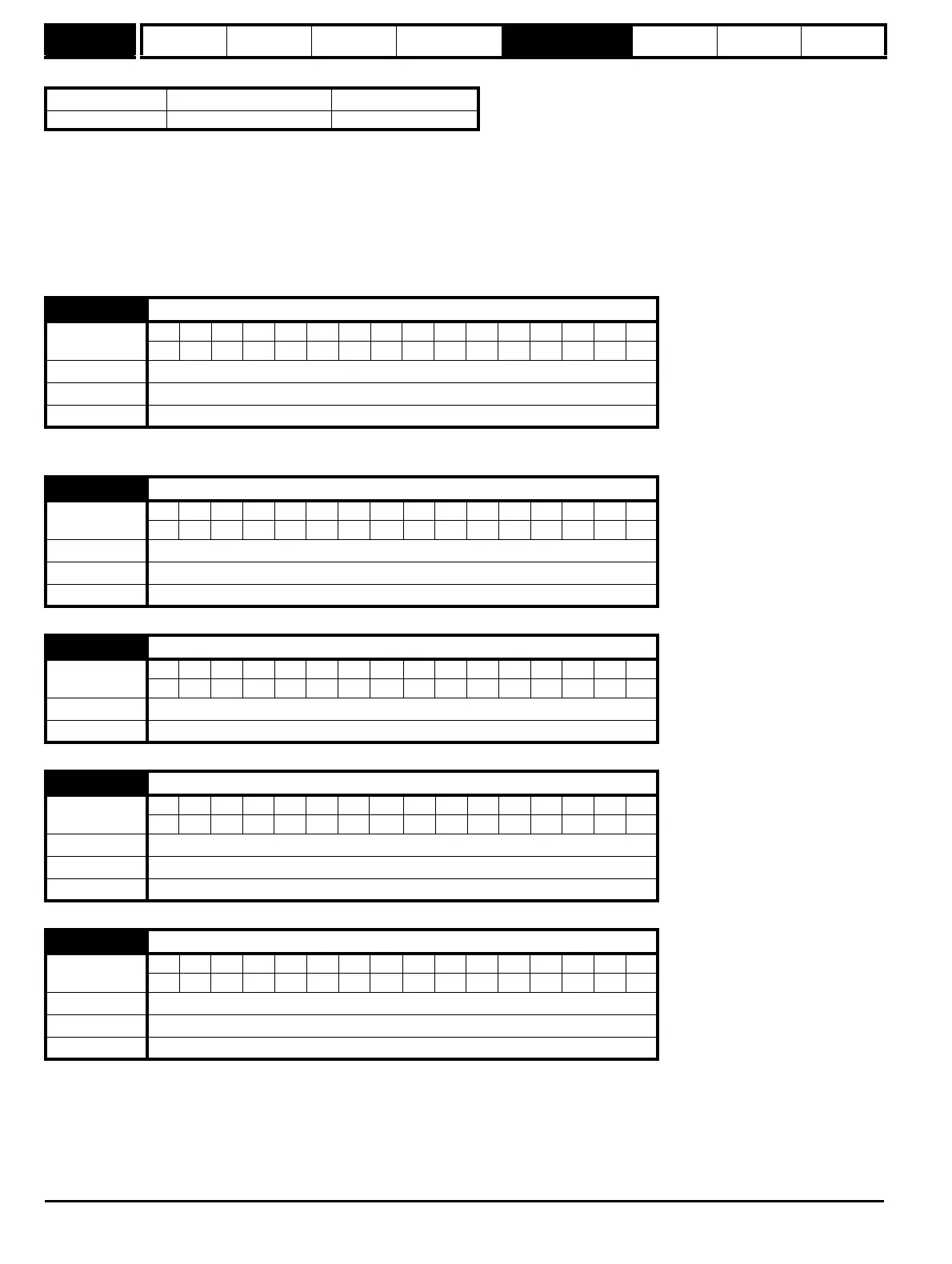
7.07 T5/6 analog input 1 offset trim
Coding
Bit SP FI DE Txt VM DP ND RA NC NV PT US RW BU PS
311
Range ±10.000 %
Default 0.000
Update rate Background read
7.08 T5/6 analog input 1 scaling
Coding
Bit SP FI DE Txt VM DP ND RA NC NV PT US RW BU PS
3111
Range 0.000 to 4.000
Default 1.000
Update rate Background read
7.09 T5/6 analog input 1 invert
Coding
Bit SP FI DE Txt VM DP ND RA NC NV PT US RW BU PS
111
Default 0
Update rate Background read
7.10 T5/6 analog input 1 destination
Coding
Bit SP FI DE Txt VM DP ND RA NC NV PT US RW BU PS
1 2 1111
Range Pr 0.00 to Pr 21.51
Default Pr 1.36
Update rate Read on drive reset
7.11 T7 analog input 2 mode
Coding
Bit SP FI DE Txt VM DP ND RA NC NV PT US RW BU PS
1 111
Range 0 to 6
Default 6
Update rate Background read