Menu 12
Parameter
structure
Keypad and
display
Parameter x.00
Parameter
description format
Advanced parameter
descriptions
Serial comms
protocol
Electronic
nameplate
Performance
156 Digitax ST Advanced User Guide
www.controltechniques.com Issue Number: 1
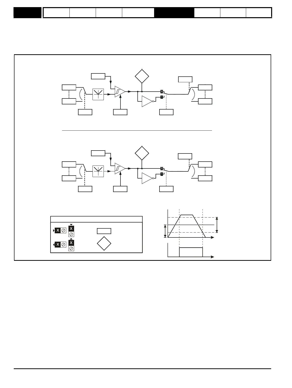
5.14 Menu 12: Threshold detectors, variable selectors and brake control function
Menu 12 includes two threshold detectors which produce logic signals depending on the level of a variable value with respect to a threshold, and two
variable selectors which allow two input parameters to be selected or combined to produce a variable output. One menu 9 or one menu 12 function is
executed every 4ms. Therefore the sample time of these functions is 4ms x number of menu 9 and 12 functions active. A function is active if one or
more sources are routed to a valid parameter.
Figure 5-11 Menu 12 logic diagram
??.??
Any variable
parameter
??.??
12.03
Threshold
Detector 1
input source
12.04
Threshold
Detector 1
threshold level
Threshold
Detector 1
Threshold
Detector 1
x(-1)
12.06
Threshold
Detector 1
output invert
12.01
Threshold
Detector 1
output indicator
12.05
Threshold
Detector 1
hysteresis
1
??.??
Any variable
parameter
??.??
12.23
Threshold
Detector 2
input source
12.24
Threshold
Detector 2
threshold level
Threshold
Detector 2
Threshold
Detector 2
x(-1)
12.26
Threshold
Detector 2
output invert
12.02
Threshold
Detector 2
output indicator
12.25
Threshold
Detector 2
hysteresis
are shown
at their default setting
(RW)
parameter
Read-only (RO)
parameter
Input
terminals
Output
terminals
Threshold
level
Threshold
output