Parameter
structure
Keypad and
display
Parameter x.00
Parameter
description format
Advanced parameter
descriptions
Serial comms
protocol
Electronic
nameplate
Performance
Menu 3
Digitax ST Advanced User Guide 63
Issue Number: 1 www.controltechniques.com
The encoder simulation source is the drive encoder input and can be any incremental type or any SINCOS type. If a SINCOS is used as the source
the simulation output is derived from the zero crossings of the sine waves and does not include interpolated information. The encoder simulation
provides an output with minimal delay from the drive encoder input. The ratio between the change of drive encoder position and the change of
encoder simulation output position is defined by Pr 3.52. The table below shows the possible ratios.
Pr 3.54 selects the format of the encoder simulation output as shown in the table below.
The marker output is derived directly from the encoder simulation input source marker. The width of the marker pulse is not adjusted with the encoder
simulation ratio, but remains the same width as the input marker. If a mode without marker lock is selected then the relationship between the marker
position and the incremental signals is undefined. If a mode with marker lock is selected the incremental position is shifted when the first input marker
occurs so that with Ab mode the marker is aligned with A high and B high, and with Fd mode the marker is aligned with F high. Marker lock is required
when the system that is receiving the encoder simulation signals requires a defined relationship between the marker and the incremental signals.
Marker lock should not be used if the drive encoder equivalent lines per revolution (ELPR) is not a power of 2 or the ELPR of the encoder simulation
output is less than 1 after the divide ratio has been applied.
5.5.1 Communication with Hiperface and EnDat encoders
It is possible to use the communications channel between the drive and a Hiperface or EnDat encoder. This allows access to the encoder functions
including reading the encoder position and, reading and writing to encoder memory. The system can be used to communicate with SC.Hiper and
SC.EnDat type encoders provided that the position checking system has been disabled, by setting Pr 90.21 to one.
To send a message to the encoder the required message must be written to the transmit register (Pr 90.22). To read the response from the encoder
the data is read from the receive register (Pr 90.23).
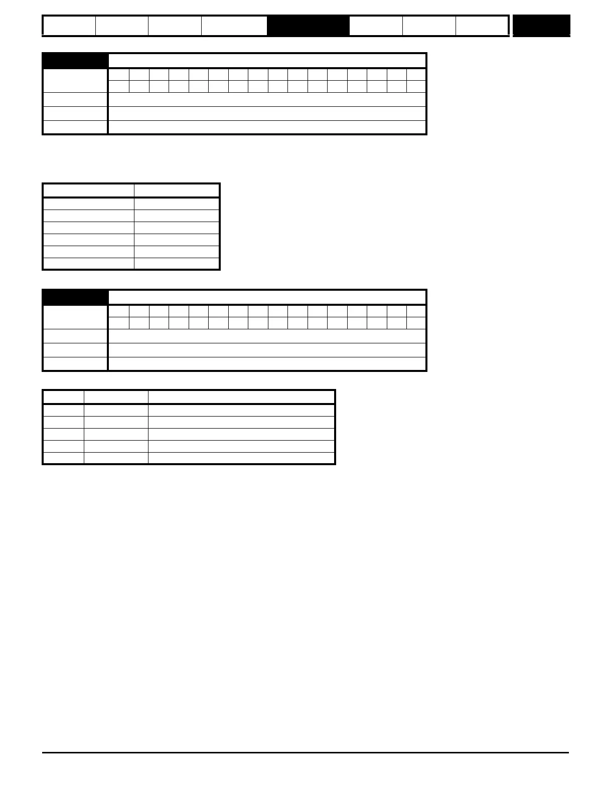
3.52
Encoder simulation ratio numerator
Coding
Bit SP FI DE Txt VM DP ND RA NC NV PT US RW BU PS
4 111
Range 0.0000 to 1.0000
Default 1.0000
Update rate Background read
Pr 3.52 Ratio
0.0000 to 0.0312 1/32
0.0313 to 0.0625 1/16
0.0626 to 0.1250 1/8
0.1251 to 0.2500 1/4
0.2501 to 0.5000 1/2
0.5001 to 1.0000 1
3.54
Encoder simulation mode
Coding
Bit SP FI DE Txt VM DP ND RA NC NV PT US RW BU PS
1 111
Range 0 to 4
Default 0
Update rate Background read
03.54 String Mode
0 Ab Quadrature outputs
1 Fd Frequency and direction outputs
2 Fr Forward and reverse outputs
3 Ab.L Quadrature outputs with marker lock
4 Fd.L Frequency and direction outputs with marker lock